

CME34M Hardware Manual - RTD Embedded Technologies, Inc.
CME34M Hardware Manual - RTD Embedded Technologies, Inc.
CME34M Hardware Manual - RTD Embedded Technologies, Inc.

Create successful ePaper yourself
Turn your PDF publications into a flip-book with our unique Google optimized e-Paper software.
Jumper Settings and Locations<br />
Many cpuModule options are configured by positioning jumpers. Jumpers are labeled on the board as JP<br />
followed by a number.<br />
Some jumpers have three pins, allowing three settings:<br />
• Pins 1 and 2 connected (indicated as “1–2”)<br />
• Pins 2 and 3 connected (indicated as “2–3”)<br />
• No pins connected<br />
1 2 3<br />
Some jumpers have two pins, allowing two settings:<br />
• Pins 1 and 2 connected (indicated as “closed”)<br />
• Pins 1 and 2 unconnected (indicated as “open”)<br />
1 2<br />
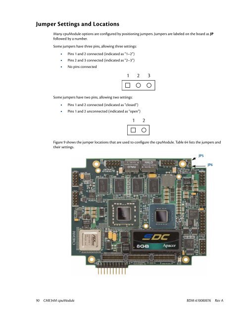
Figure 9 shows the jumper locations that are used to configure the cpuModule. Table 64 lists the jumpers and<br />
their settings.<br />
JP5<br />
JP6<br />
90 <strong>CME34M</strong> cpuModule BDM-610000076 Rev A


