

CME34M Hardware Manual - RTD Embedded Technologies, Inc.
CME34M Hardware Manual - RTD Embedded Technologies, Inc.
CME34M Hardware Manual - RTD Embedded Technologies, Inc.

You also want an ePaper? Increase the reach of your titles
YUMPU automatically turns print PDFs into web optimized ePapers that Google loves.
Serial Port 1 (CN7) and Serial Port 2 (CN8)<br />
Serial Port 1 (COM1) is implemented on connector CN7, and Serial Port 2 is implemented on connector CN8.<br />
The serial ports are normally configured as PC compatible full-duplex RS-232 ports, but you may use the BIOS<br />
Setup program to reconfigure these ports as half-duplex RS-422 or full-duplex RS-422 or RS-485. If you<br />
reconfigure the ports, you must also select the I/O address and corresponding interrupt using Setup. Table 13<br />
provides the standard I/O addresses and corresponding interrupts.<br />
Table 13<br />
Serial Port Settings<br />
I/O Address (hex)<br />
03F8<br />
02F8<br />
03E8<br />
02E8<br />
IRQ<br />
IRQ4<br />
IRQ3<br />
IRQ4<br />
IRQ3<br />
Serial Port UART<br />
The serial ports are implemented with a 16550-compatible UART (Universal Asynchronous Receiver/<br />
Transmitter). This UART is capable of baud rates up to 115.2 kbaud in 16450 and 16550A compatible mode, and<br />
includes a 16-byte FIFO. Refer to any standard PC-AT hardware reference for the register map of the UART. For<br />
more information about programming UARTs, refer to Appendix D.<br />
RS-232 Serial Port (Default)<br />
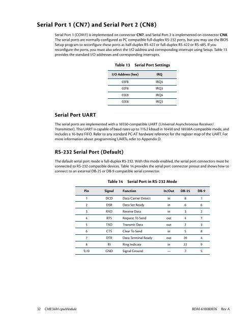
The default serial port mode is full-duplex RS-232. With this mode enabled, the serial port connectors must be<br />
connected to RS-232 compatible devices. Table 14 provides the serial port connector pinout and shows how to<br />
connect to an external DB-25 or DB-9 compatible serial connector.<br />
Table 14<br />
Serial Port in RS-232 Mode<br />
Pin Signal Function In/Out DB-25 DB-9<br />
1 DCD Data Carrier Detect in 8 1<br />
2 DSR Data Set Ready in 6 6<br />
3 RXD Receive Data in 3 2<br />
4 RTS Request To Send out 4 7<br />
5 TXD Transmit Data out 2 3<br />
6 CTS Clear To Send in 5 8<br />
7 DTR Data Terminal Ready out 20 4<br />
8 RI Ring Indicate in 22 9<br />
9,10 GND Signal Ground — 7 5<br />
32 <strong>CME34M</strong> cpuModule BDM-610000076 Rev A


