

CME34M Hardware Manual - RTD Embedded Technologies, Inc.
CME34M Hardware Manual - RTD Embedded Technologies, Inc.
CME34M Hardware Manual - RTD Embedded Technologies, Inc.

You also want an ePaper? Increase the reach of your titles
YUMPU automatically turns print PDFs into web optimized ePapers that Google loves.
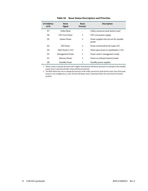
Table 58<br />
Reset Status Description and Priorities<br />
I/O Address<br />
457h<br />
Reset<br />
Signal<br />
Reset<br />
Priority 1<br />
Description<br />
D7 Utility Reset - Utility connector push button reset 2<br />
D6 CPU Core Power 5 CPU core powers supply<br />
D5 System Power 4 Power supplies that are not for standby<br />
power<br />
D4 SIO Power 3 Power monitored by the Super I/O.<br />
D3 Main Power (+5V) 2 Main input power to cpuModule (+5V)<br />
D2 Management Power 2 Power used in management mode.<br />
D1 Memory Power 2 Power to onboard memory banks<br />
D0 Standby Power 1 Standby power supplies<br />
1. When a reset is asserted, all resets with a higher reset priority will also be asserted. For example, if the standby<br />
power reset is asserted, all other resets will also be asserted.<br />
2. The BIOS allows the user to change the function of the utility connector’s push button reset. Even if the push<br />
button is not configured as a reset, this bit will always read a 1(asserted) when the reset button has been<br />
pushed.<br />
72 <strong>CME34M</strong> cpuModule BDM-610000076 Rev A


