

CME34M Hardware Manual - RTD Embedded Technologies, Inc.
CME34M Hardware Manual - RTD Embedded Technologies, Inc.
CME34M Hardware Manual - RTD Embedded Technologies, Inc.

Create successful ePaper yourself
Turn your PDF publications into a flip-book with our unique Google optimized e-Paper software.
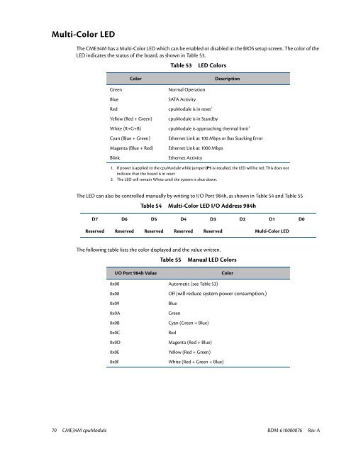
Multi-Color LED<br />
The <strong>CME34M</strong> has a Multi-Color LED which can be enabled or disabled in the BIOS setup screen. The color of the<br />
LED indicates the status of the board, as shown in Table 53.<br />
Table 53<br />
LED Colors<br />
Color<br />
Description<br />
Green<br />
Blue<br />
Normal Operation<br />
SATA Activity<br />
Red cpuModule is in reset 1<br />
Yellow (Red + Green)<br />
cpuModule is in Standby<br />
White (R+G+B) cpuModule is approaching thermal limit 2<br />
Cyan (Blue + Green)<br />
Magenta (Blue + Red)<br />
Blink<br />
Ethernet Link at 100 Mbps or Bus Stacking Error<br />
Ethernet Link at 1000 Mbps<br />
Ethernet Activity<br />
1. If power is applied to the cpuModule while jumper JP5 is installed, the LED will be red. This does not<br />
indicate that the board is in reset<br />
2. The LED will remain White until the system is shut down.<br />
The LED can also be controlled manually by writing to I/O Port 984h, as shown in Table 54 and Table 55<br />
Table 54 Multi-Color LED I/O Address 984h<br />
D7 D6 D5 D4 D3 D2 D1 D0<br />
Reserved Reserved Reserved Reserved Reserved Multi-Color LED<br />
The following table lists the color displayed and the value written.<br />
Table 55 <strong>Manual</strong> LED Colors<br />
I/O Port 984h Value<br />
Color<br />
0x00 Automatic (see Table 53)<br />
0x08<br />
Off (will reduce system power consumption.)<br />
0x09<br />
Blue<br />
0x0A<br />
Green<br />
0x0B<br />
Cyan (Green + Blue)<br />
0x0C<br />
Red<br />
0x0D<br />
Magenta (Red + Blue)<br />
0x0E<br />
Yellow (Red + Green)<br />
0x0F<br />
White (Red + Green + Blue)<br />
70 <strong>CME34M</strong> cpuModule BDM-610000076 Rev A


