

CME34M Hardware Manual - RTD Embedded Technologies, Inc.
CME34M Hardware Manual - RTD Embedded Technologies, Inc.
CME34M Hardware Manual - RTD Embedded Technologies, Inc.

You also want an ePaper? Increase the reach of your titles
YUMPU automatically turns print PDFs into web optimized ePapers that Google loves.
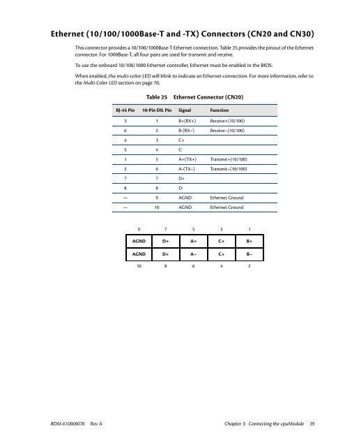
Ethernet (10/100/1000Base-T and -TX) Connectors (CN20 and CN30)<br />
This connector provides a 10/100/1000Base-T Ethernet connection. Table 25 provides the pinout of the Ethernet<br />
connector. For 1000Base-T, all four pairs are used for transmit and receive.<br />
To use the onboard 10/100/1000 Ethernet controller, Ethernet must be enabled in the BIOS.<br />
When enabled, the multi-color LED will blink to indicate an Ethernet connection. For more information, refer to<br />
the Multi-Color LED section on page 70.<br />
Table 25<br />
Ethernet Connector (CN20)<br />
RJ-45 Pin 10-Pin DIL Pin Signal Function<br />
3 1 B+(RX+) Receive+(10/100)<br />
6 2 B-(RX–) Receive–(10/100)<br />
4 3 C+<br />
5 4 C-<br />
1 5 A+(TX+) Transmit+(10/100)<br />
2 6 A-(TX–) Transmit–(10/100)<br />
7 7 D+<br />
8 8 D-<br />
— 9 AGND Ethernet Ground<br />
— 10 AGND Ethernet Ground<br />
9 7 5 3 1<br />
AGND D+ A+ C+ B+<br />
AGND D+ A– C+ B–<br />
10 8 6 4 2<br />
BDM-610000076 Rev A Chapter 3: Connecting the cpuModule 39


