

CME34M Hardware Manual - RTD Embedded Technologies, Inc.
CME34M Hardware Manual - RTD Embedded Technologies, Inc.
CME34M Hardware Manual - RTD Embedded Technologies, Inc.

Create successful ePaper yourself
Turn your PDF publications into a flip-book with our unique Google optimized e-Paper software.
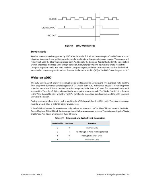
Figure 6<br />
aDIO Match Mode<br />
Strobe Mode<br />
Another interrupt mode supported by aDIO is Strobe mode. This allows the strobe pin of the DIO connector to<br />
trigger an interrupt. A low to high transition on the strobe pin will cause an interrupt request. The request will<br />
remain high until the Clear Register is read from. Additionally, the Compare Register latched in the value at Port<br />
0 when the Strobe pin made a low to high transition. No further strobes will be available until a read of the<br />
Compare Register is made. You must read the Compare Register, and then clear interrupts so that the latched<br />
value in the compare register is not lost. To enter Strobe mode, set bits [4:3] of the DIO-Control register to “01”.<br />
Wake-on-aDIO<br />
The aDIO Strobe, Match and Event interrupt can be used to generate a wake event. This event can wake the CPU<br />
from any power-down mode, including Soft-Off (S5). Wake from aDIO will work as long at +5V Standby power<br />
is applied to the board. To use the aDIO to wake the system, Wake from aDIO must first be enabled in the BIOS<br />
setup utility. Then the aDIO is configured in the appropriate interrupt mode. The “Wake Enable” bit is then set<br />
in the Wake Control Register at 0x9C4. The CPU can then be placed in a standby mode, and the aDIO interrupt<br />
will wake the system.<br />
During system standby, a 32kHz clock is used for the aDIO instead of an 8.33 MHz clock. Therefore, transitions<br />
must be at least 30 us in order to trigger a wake event.<br />
If the aDIO is to be used for a wake event only, and not an interrupt, the “Int Mask” bit can be set in the Wake<br />
Control Register. This will block the interrupt, but still allow a wake event to occur. The various settings for “Wake<br />
Enable” and “Int Mask” are shown in Table 49 below.<br />
Table 49 Interrupt and Wake Event Generation<br />
WakeEnable Int Mask Function<br />
0 0 Interrupt Only<br />
0 1 No Interrupt or Wake event is generated<br />
1 0 Interrupt and Wake Event<br />
1 1 Wake Event Only<br />
BDM-610000076 Rev A Chapter 4: Using the cpuModule 63


