PIC24HJ64 Datasheet
PIC24HJ64 Datasheet
PIC24HJ64 Datasheet

Create successful ePaper yourself
Turn your PDF publications into a flip-book with our unique Google optimized e-Paper software.
PIC24HJ32GP302/304, <strong>PIC24HJ64</strong>GPX02/X04, AND PIC24HJ128GPX02/X04<br />
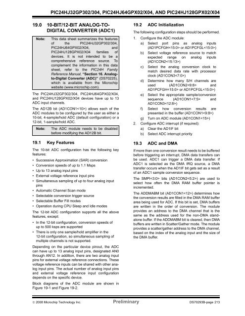
19.0 10-BIT/12-BIT ANALOG-TO-<br />
DIGITAL CONVERTER (ADC1)<br />
Note:<br />
The PIC24HJ32GP302/304, <strong>PIC24HJ64</strong>GPX02/X04,<br />
and PIC24HJ128GPX02/X04 devices have up to 13<br />
ADC input channels.<br />
The AD12B bit (AD1CON1) allows each of the<br />
ADC modules to be configured by the user as either a<br />
10-bit, 4-sample/hold ADC (default configuration) or a<br />
12-bit, 1-sample/hold ADC.<br />
Note:<br />
This data sheet summarizes the features<br />
of the PIC24HJ32GP302/304,<br />
<strong>PIC24HJ64</strong>GPX02/X04,<br />
and<br />
PIC24HJ128GPX02/X04 families of<br />
devices. It is not intended to be a<br />
comprehensive reference source. To<br />
complement the information in this data<br />
sheet, refer to the PIC24H Family<br />
Reference Manual, “Section 16. Analogto-Digital<br />
Converter (ADC)” (DS70225),<br />
which is available from the Microchip<br />
website (www.microchip.com).<br />
The ADC module needs to be disabled<br />
before modifying the AD12B bit.<br />
19.1 Key Features<br />
The 10-bit ADC configuration has the following key<br />
features:<br />
• Successive Approximation (SAR) conversion<br />
• Conversion speeds of up to 1.1 Msps<br />
• Up to 13 analog input pins<br />
• External voltage reference input pins<br />
• Simultaneous sampling of up to four analog input<br />
pins<br />
• Automatic Channel Scan mode<br />
• Selectable conversion trigger source<br />
• Selectable Buffer Fill modes<br />
• Operation during CPU Sleep and Idle modes<br />
The 12-bit ADC configuration supports all the above<br />
features, except:<br />
• In the 12-bit configuration, conversion speeds of<br />
up to 500 ksps are supported<br />
• There is only one sample/hold amplifier in the<br />
12-bit configuration, so simultaneous sampling of<br />
multiple channels is not supported.<br />
Depending on the particular device pinout, the ADC<br />
can have up to 13 analog input pins, designated AN0<br />
through AN12. In addition, there are two analog input<br />
pins for external voltage reference connections. These<br />
voltage reference inputs can be shared with other analog<br />
input pins. The actual number of analog input pins<br />
and external voltage reference input configuration<br />
depends on the specific device.<br />
Block diagrams of the ADC module are shown in<br />
Figure 19-1 and Figure 19-2.<br />
19.2 ADC Initialization<br />
The following configuration steps should be performed.<br />
1. Configure the ADC module:<br />
a) Select port pins as analog inputs<br />
(AD1PCFGH or AD1PCFGL)<br />
b) Select voltage reference source to match<br />
expected range on analog inputs<br />
(AD1CON2)<br />
c) Select the analog conversion clock to<br />
match desired data rate with processor<br />
clock (AD1CON3)<br />
d) Determine how many S/H channels are<br />
used (AD1CON2 and<br />
AD1PCFGH or AD1PCFGL)<br />
e) Select the appropriate sample/conversion<br />
sequence (AD1CON1 and<br />
AD1CON3)<br />
f) Select how conversion results are<br />
presented in the buffer (AD1CON1)<br />
g) Turn on ADC module (AD1CON1)<br />
2. Configure ADC interrupt (if required):<br />
a) Clear the AD1IF bit<br />
b) Select ADC interrupt priority<br />
19.3 ADC and DMA<br />
If more than one conversion result needs to be buffered<br />
before triggering an interrupt, DMA data transfers can<br />
be used. ADC1 can trigger a DMA data transfer. If<br />
ADC1 is selected as the DMA IRQ source, a DMA<br />
transfer occurs when the AD1IF bit gets set as a result<br />
of an ADC1 sample conversion sequence.<br />
The SMPI bits (AD1CON2) are used to<br />
select how often the DMA RAM buffer pointer is<br />
incremented.<br />
The ADDMABM bit (AD1CON1) determines how<br />
the conversion results are filled in the DMA RAM buffer<br />
area being used for ADC. If this bit is set, DMA buffers<br />
are written in the order of conversion. The module<br />
provides an address to the DMA channel that is the<br />
same as the address used for the non-DMA standalone<br />
buffer. If the ADDMABM bit is cleared, then DMA<br />
buffers are written in Scatter/Gather mode. The module<br />
provides a scatter/gather address to the DMA channel,<br />
based on the index of the analog input and the size of<br />
the DMA buffer.<br />
© 2008 Microchip Technology Inc. Preliminary DS70293B-page 213