Benutzerhandbuch / User Manual - TR Electronic
Benutzerhandbuch / User Manual - TR Electronic
Benutzerhandbuch / User Manual - TR Electronic

You also want an ePaper? Increase the reach of your titles
YUMPU automatically turns print PDFs into web optimized ePapers that Google loves.
Installation / Preparation for Commissioning<br />
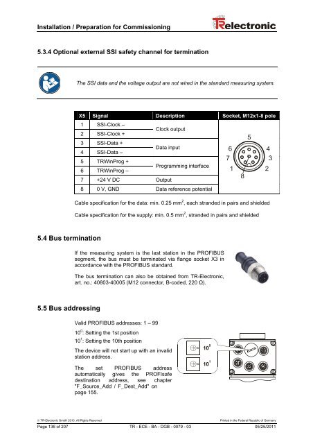
5.3.4 Optional external SSI safety channel for termination<br />
The SSI data and the voltage output are not wired in the standard measuring system.<br />
X5 Signal Description Socket, M12x1-8 pole<br />
1 SSI-Clock –<br />
Clock output<br />
2 SSI-Clock +<br />
3 SSI-Data +<br />
Data input<br />
4 SSI-Data –<br />
5 <strong>TR</strong>WinProg +<br />
Programming interface<br />
6 <strong>TR</strong>WinProg –<br />
7 +24 V DC Output<br />
8 0 V, GND Data reference potential<br />
Cable specification for the data: min. 0.25 mm 2 , each stranded in pairs and shielded<br />
Cable specification for the supply: min. 0.5 mm 2 , stranded in pairs and shielded<br />
5.4 Bus termination<br />
If the measuring system is the last station in the PROFIBUS<br />
segment, the bus must be terminated via flange socket X3 in<br />
accordance with the PROFIBUS standard.<br />
The bus termination can also be obtained from <strong>TR</strong>-<strong>Electronic</strong>,<br />
art. no.: 40803-40005 (M12 connector, B-coded, 220 Ω).<br />
5.5 Bus addressing<br />
Valid PROFIBUS addresses: 1 – 99<br />
10 0 : Setting the 1st position<br />
10 1 : Setting the 10th position<br />
The device will not start up with an invalid<br />
station address.<br />
The set PROFIBUS address<br />
automatically gives the PROFIsafe<br />
destination address, see chapter<br />
"F_Source_Add / F_Dest_Add" on<br />
page 155.<br />
© <strong>TR</strong>-<strong>Electronic</strong> GmbH 2010, All Rights Reserved Printed in the Federal Republic of Germany<br />
Page 136 of 207 <strong>TR</strong> - ECE - BA - DGB - 0079 - 03 05/25/2011