Benutzerhandbuch / User Manual - TR Electronic
Benutzerhandbuch / User Manual - TR Electronic
Benutzerhandbuch / User Manual - TR Electronic

You also want an ePaper? Increase the reach of your titles
YUMPU automatically turns print PDFs into web optimized ePapers that Google loves.
PROFIBUS / PROFIsafe - Commissioning<br />
6.1.2 Device master file (GSD)<br />
In order to achieve a simple plug-and-play configuration for PROFIBUS, the<br />
characteristic communication features for PROFIBUS devices were defined in the<br />
form of an electronic device data sheet (device master file, GSD file).<br />
Using the defined file format, the configuration system can easily read in the device<br />
master data of the PROFIBUS measuring system and automatically take account of it<br />
in the bus system configuration.<br />
The GSD file is a constituent of the measuring system and has the file name<br />
"<strong>TR</strong>000CE3.GSE" (English). The measuring system also has three bitmap files called<br />
"<strong>TR</strong>0E_BDE.bmp", "<strong>TR</strong>0E_BDI.bmp" and "<strong>TR</strong>0E_BSF.bmp", which it displays in<br />
normal mode, in diagnostic mode and in special operating states.<br />
The files are contained on the software/support DVD:<br />
Art. no.: 490-01001, Software no.: 490-00406.<br />
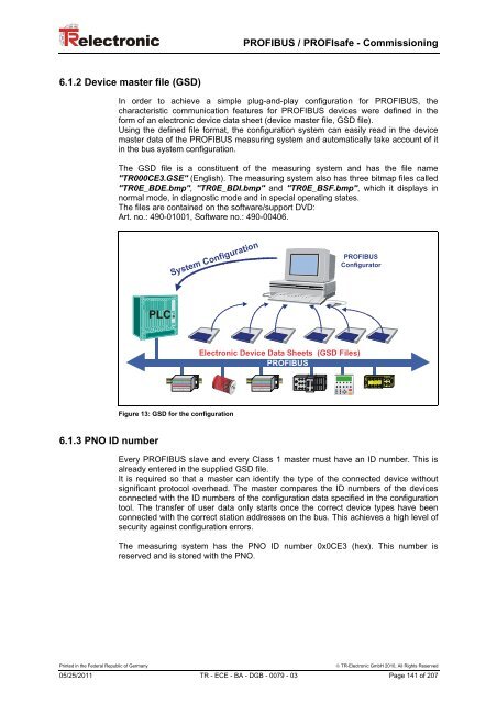
System Configuration<br />
PROFIBUS<br />
Configurator<br />
PLC<br />
<strong>Electronic</strong> Device Data Sheets (GSD Files)<br />
PROFIBUS<br />
Figure 13: GSD for the configuration<br />
6.1.3 PNO ID number<br />
Every PROFIBUS slave and every Class 1 master must have an ID number. This is<br />
already entered in the supplied GSD file.<br />
It is required so that a master can identify the type of the connected device without<br />
significant protocol overhead. The master compares the ID numbers of the devices<br />
connected with the ID numbers of the configuration data specified in the configuration<br />
tool. The transfer of user data only starts once the correct device types have been<br />
connected with the correct station addresses on the bus. This achieves a high level of<br />
security against configuration errors.<br />
The measuring system has the PNO ID number 0x0CE3 (hex). This number is<br />
reserved and is stored with the PNO.<br />
Printed in the Federal Republic of Germany<br />
© <strong>TR</strong>-<strong>Electronic</strong> GmbH 2010, All Rights Reserved<br />
05/25/2011 <strong>TR</strong> - ECE - BA - DGB - 0079 - 03 Page 141 of 207