Benutzerhandbuch / User Manual - TR Electronic
Benutzerhandbuch / User Manual - TR Electronic
Benutzerhandbuch / User Manual - TR Electronic

You also want an ePaper? Increase the reach of your titles
YUMPU automatically turns print PDFs into web optimized ePapers that Google loves.
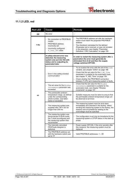
Troubleshooting and Diagnosis Options<br />
11.1.2 LED, red<br />
Red LED Cause Remedy<br />
Off No error –<br />
1 Hz<br />
− No connection to PROFIBUS<br />
master<br />
− PROFIBUS address<br />
incorrectly set<br />
− Incorrectly configured<br />
F_iPar_CRC value<br />
− The PROFIBUS address set with the hardware<br />
switch must match the projected PROFIBUS<br />
address<br />
− The checksum calculated for the defined<br />
iParameter set is incorrect, or was not included<br />
in the projection, see chapter "Parameter<br />
Definition / CRC Calculation" on page 159<br />
on<br />
A safety-relevant error was<br />
detected, the measuring<br />
system was put into fail-safe<br />
status and is outputting its<br />
passivated data:<br />
− Error in the safety-oriented<br />
communication<br />
− The set value for the Window<br />
increments parameter was<br />
exceeded<br />
− The permissible ambient<br />
temperature range, as defined<br />
under the corresponding<br />
article number, was fallen<br />
below or exceeded<br />
− The measuring system was<br />
supplied with >36 V DC for<br />
longer than 200 ms<br />
− The measuring system was<br />
disconnected in RUN mode,<br />
the F-Host reconfigured and<br />
the measuring system then<br />
reconnected<br />
− The internally calculated<br />
PROFIsafe telegram is<br />
defective<br />
− The PROFIBUS address set<br />
with the hardware switch was<br />
set to "0"<br />
In order to restart the measuring system after a<br />
passivation the error must generally be<br />
eliminated first of all and then the supply<br />
voltage switched OFF/ON.<br />
− Try to localize the error with the aid of the DIAG<br />
variable, see chapter "DIAG" on page 186<br />
− Check that the set value for the F_WD_Time<br />
parameter is suitable for the automation task,<br />
see chapter "F_WD_Time" on page 155<br />
− Check whether the PROFIBUS connection<br />
between F-CPU and measuring system is faulty<br />
− Check that the set value for the Window<br />
increments parameter is suitable for the<br />
automation task, see chapter "Window<br />
increments" on page 157<br />
− Suitable measures must be taken to ensure that<br />
the permissible ambient temperature range can<br />
be observed at all times<br />
− The measuring system must be shut down<br />
immediately and checked in the factory. When<br />
sending the measuring system to the factory, the<br />
reasons and circumstances relating to the<br />
overvoltage must be specified<br />
− The configuration must only be transferred to the<br />
measuring system in STOP status in the start-up<br />
phase<br />
− Power supply OFF/ON. If the error persists after<br />
this measure, the measuring system must be<br />
replaced<br />
− Valid PROFIBUS addresses: 1 – 99<br />
© <strong>TR</strong>-<strong>Electronic</strong> GmbH 2010, All Rights Reserved Printed in the Federal Republic of Germany<br />
Page 192 of 207 <strong>TR</strong> - ECE - BA - DGB - 0079 - 03 05/25/2011