principles and applications of microearthquake networks
principles and applications of microearthquake networks
principles and applications of microearthquake networks

Create successful ePaper yourself
Turn your PDF publications into a flip-book with our unique Google optimized e-Paper software.
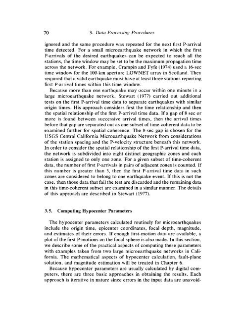
70 3. Data Processirig Procedures<br />
ignored <strong>and</strong> the same procedure was repeated for the next first P-arrival<br />
time detected. For a small <strong>microearthquake</strong> network in which the first<br />
P-arrivals <strong>of</strong> the desired earthquakes can be expected to reach all the<br />
stations, the time window may be set to be the maximum propagation time<br />
across the network. For example, Crampin <strong>and</strong> Fyfe (1974) used a 16-sec<br />
time window for the 100-km aperture LOWNET array in Scotl<strong>and</strong>. They<br />
required that a valid earthquake must have at least three stations reporting<br />
first P-arrival times within this time window.<br />
Because more than one earthquake may occur within one minute in a<br />
large <strong>microearthquake</strong> network, Stewart (1977) carried out additional<br />
tests on the first P-arrival time data to separate earthquakes with similar<br />
origin times. His approach considers first the time relationship <strong>and</strong> then<br />
the spatial relationship <strong>of</strong> the first P-arrival time data. If a gap <strong>of</strong> 8 sec or<br />
more is found between successive arrival times, then the arrival times<br />
before that gap are separated out as one subset <strong>of</strong> time-coherent data to be<br />
examined further for spatial coherence. The 8-sec gap is chosen for the<br />
USGS Central California Microearthquake Network from considerations<br />
<strong>of</strong> the station spacing <strong>and</strong> the P-velocity structure beneath this network.<br />
In order to consider the spatial relationship <strong>of</strong> the first P-arrival time data,<br />
the network is subdivided into eight distinct geographic zones <strong>and</strong> each<br />
station is assigned to only one zone. For a given subset <strong>of</strong> time-coherent<br />
data, the number <strong>of</strong> first P-arrivals in pairs <strong>of</strong> adjacent zones is counted. If<br />
this number is greater than 3, then the first P-arrival time data in such<br />
zones are considered to belong to one earthquake event. If this is not the<br />
case, then those data that fail the test are discarded <strong>and</strong> the remaining data<br />
in this time-coherent subset are examined in a similar manner. The details<br />
<strong>of</strong> this approach are described in Stewart (1977).<br />
3.5. Computing Hypocenter Parameters<br />
The hypocenter parameters calculated routinely for <strong>microearthquake</strong>s<br />
include the origin time, epicenter coordinates, focal depth, magnitude,<br />
<strong>and</strong> estimates <strong>of</strong> their errors. If enough first-motion data are available, a<br />
plot <strong>of</strong> the first P-motions on the focal sphere is also made. In this section,<br />
we describe some <strong>of</strong> the practical aspects <strong>of</strong> computing these parameters<br />
with examples taken from two large <strong>microearthquake</strong> <strong>networks</strong> in California.<br />
The mathematical aspects <strong>of</strong> hypocenter calculation, fault-plane<br />
solution, <strong>and</strong> magnitude estimation will be treated in Chapter 6.<br />
Because hypocenter parameters are usually calculated by digital computers,<br />
there are three basic approaches in obtaining the results. Each<br />
approach is iterative in nature since errors in the input data are unavoid-