Introduction to Digital Signal and System Analysis - Tutorsindia
Introduction to Digital Signal and System Analysis - Tutorsindia
Introduction to Digital Signal and System Analysis - Tutorsindia

Create successful ePaper yourself
Turn your PDF publications into a flip-book with our unique Google optimized e-Paper software.
<strong>Introduction</strong> <strong>to</strong> <strong>Digital</strong> <strong>Signal</strong> <strong>and</strong> <strong>System</strong> <strong>Analysis</strong><br />
Time-domain <strong>Analysis</strong><br />
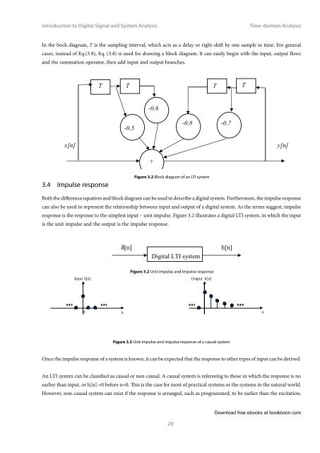
In the bock diagram, T is the sampling interval, which acts as a delay or right-shift by one sample in time. For general<br />
cases, instead of Eq.(3.9), Eq. (3.8) is used for drawing a block diagram. It can easily begin with the input, output flows<br />
<strong>and</strong> the summation opera<strong>to</strong>r, then add input <strong>and</strong> output branches.<br />
T T T T<br />
-0.6<br />
-0.5<br />
-0.8<br />
-0.7<br />
x[n]<br />
y[n]<br />
+<br />
3.4 Impulse response<br />
Figure 3.2 Block diagram of an LTI system<br />
Both the difference equation <strong>and</strong> block diagram can be used <strong>to</strong> describe a digital system. Furthermore, the impulse response<br />
can also be used <strong>to</strong> represent the relationship between input <strong>and</strong> output of a digital system. As the terms suggest, impulse<br />
response is the response <strong>to</strong> the simplest input – unit impulse. Figure 3.2 illustrates a digital LTI system, in which the input<br />
is the unit impulse <strong>and</strong> the output is the impulse response.<br />
δ[n]<br />
<strong>Digital</strong> LTI system<br />
h[n]<br />
Input d[n]<br />
Figure 3.2 Unit impulse <strong>and</strong> impulse response<br />
Output h[n]<br />
0 n n<br />
Figure 3.3 Unit impulse <strong>and</strong> impulse response of a causal system<br />
Once the impulse response of a system is known, it can be expected that the response <strong>to</strong> other types of input can be derived.<br />
An LTI system can be classified as causal or non-causal. A causal system is refereeing <strong>to</strong> those in which the response is no<br />
earlier than input, or h[n] =0 before n=0. This is the case for most of practical systems or the systems in the natural world.<br />
However, non-causal system can exist if the response is arranged, such as programmed, <strong>to</strong> be earlier than the excitation.<br />
29<br />
Download free ebooks at bookboon.com