Flo-Ware Manual - Hachflow
Flo-Ware Manual - Hachflow
Flo-Ware Manual - Hachflow

You also want an ePaper? Increase the reach of your titles
YUMPU automatically turns print PDFs into web optimized ePapers that Google loves.
Device communication<br />
Option<br />
Primary Call Interval<br />
Secondary Call Interval<br />
SMS to E-mail Gateway<br />
SMS Service Center<br />
Server Verification<br />
Code<br />
Description<br />
The frequency that the logger calls the server, not to exceed the<br />
logging interval. Options: 5, 6, 10, 12, 15, 30, 60 minutes; 2, 3, 4,<br />
6, 12, 24 hours.<br />
The frequency that the logger calls the server during an alarm<br />
condition. Options: 5, 6, 10, 12, 15, 30, 60 minutes; 2, 3, 4, 6, 12,<br />
24 hours.<br />
GPRS only—completed automatically when the provider is<br />
selected.<br />
GPRS only—completed automatically after the provider is<br />
selected.<br />
The customer-specific ID that connects an instrument to the<br />
customer account during telemetry.<br />
4.1.4.4 Datalog setup<br />
Use the datalog setup menu to specify which channels will be recorded in the datalog. A<br />
channel can be a reading from an attached sensor, the battery voltage from the logger or<br />
a statistical value based on a sensor reading. A channel must be selected before any<br />
data can be saved. A maximum of 16 channels can be selected.<br />
Note: If channels are added to or removed from an existing program, all data in the logger will be<br />
erased. Be sure to download the data from the logger to a safe location before the modified<br />
program is written to the logger.<br />
1. Click on the Programming tab in the FL900 Series Driver window. If online, the<br />
attached sensors and ports are shown.<br />
2. If offline, click on the Datalog Setup menu. Select the sensor(s) from the drop-down<br />
list in the Port Assignments section that agree with the sensor and port configurations<br />
on the logger.<br />
3. Click on the Datalog Setup menu.<br />
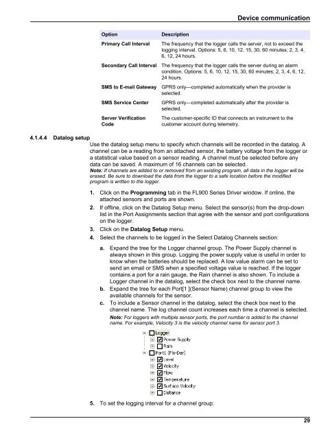
4. Select the channels to be logged in the Select Datalog Channels section:<br />
a. Expand the tree for the Logger channel group. The Power Supply channel is<br />
always shown in this group. Logging the power supply value is useful in order to<br />
know when the batteries should be replaced. A low value alarm can be set to<br />
send an email or SMS when a specified voltage value is reached. If the logger<br />
contains a port for a rain gauge, the Rain channel is also shown. To include a<br />
Logger channel in the datalog, select the check box next to the channel name.<br />
b. Expand the tree for each Port[1 ](Sensor Name) channel group to view the<br />
available channels for the sensor.<br />
c. To include a Sensor channel in the datalog, select the check box next to the<br />
channel name. The log channel count increases each time a channel is selected.<br />
Note: For loggers with multiple sensor ports, the port number is added to the channel<br />
name. For example, Velocity 3 is the velocity channel name for sensor port 3.<br />
5. To set the logging interval for a channel group:<br />
29