Flo-Ware Manual - Hachflow
Flo-Ware Manual - Hachflow
Flo-Ware Manual - Hachflow

Create successful ePaper yourself
Turn your PDF publications into a flip-book with our unique Google optimized e-Paper software.
Device communication<br />
Note: The Calibration Complete screen shows the values that were entered by the user and<br />
the values that were measured by the sensor. If the values are different, the calibration<br />
adjustment value or multiplier is shown.<br />
7. Click WRITE TO LOGGER to save the settings. A message window is shown:<br />
Option<br />
Warning: all data<br />
will be lost.<br />
Continue?<br />
Description<br />
All data that is stored in the logger is erased when a program is written to<br />
the logger. To save the data, select No and download the data to a safe<br />
location. Select Yes to erase all data and update the logger with the new<br />
program.<br />
Set Logger Clock Synchronize to Computer Clock—the logger uses the date and time<br />
settings of the computer. Set Logger Clock—the logger uses the date<br />
and time settings that are set by the user. If the unit has a modem, the<br />
logger automatically uses the date and time settings of the server.<br />
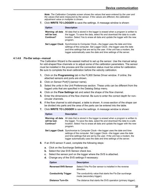
4.1.4.6 <strong>Flo</strong>-Dar setup—manual<br />
The Calibration Wizard is the easiest method to set up the sensor. Use the manual setup<br />
for odd-shaped flow channels or to adjust some of the calibration parameters. The sensor<br />
must be installed in the process and the connection status must be online for calibration.<br />
Be sure to complete the level calibration before the velocity calibration.<br />
1. Click on the Programming tab in the FL900 Series Driver window. If online, the<br />
attached sensors and ports are shown.<br />
2. Click on Sensor Port[1] (sensor name).<br />
3. Select the units in the Unit Preferences section. These units can be different from the<br />
logged units that are specified in the Datalog Setup menu.<br />
4. Click on the <strong>Flo</strong>w Settings tab and select the shape of the flow channel.<br />
5. Enter the dimensions of the flow channel. Be sure to enter the correct depth for noncircular<br />
channels.<br />
6. If the flow channel is odd-shaped, a table is shown. A cross-section of the shape can<br />
be divided into parts and the area of the parts can be entered into the table.<br />
7. Click WRITE TO LOGGER to save the settings. A message window is shown:<br />
Option<br />
Warning: all data<br />
will be lost.<br />
Continue?<br />
Description<br />
All data that is stored in the logger is erased when a program is written to<br />
the logger. To save the data, select No and download the data to a safe<br />
location. Select Yes to erase all data and update the logger with the new<br />
program.<br />
Set Logger Clock Synchronize to Computer Clock—the logger uses the date and time<br />
settings of the computer. Set Logger Clock—the logger uses the date<br />
and time settings that are set by the user. If the unit has a modem, the<br />
logger automatically uses the date and time settings of the server.<br />
8. If an SVS sensor if used, complete the following steps:<br />
a. Click on the Surcharge Settings tab.<br />
b. Select the Use SVS Sensor check box.<br />
c. Select the sensor port on the logger where the SVS is attached.<br />
d. Change any of the SVS settings if necessary:<br />
Option<br />
Reversed SVS Sensor<br />
Conductivity Trigger<br />
Distance Turn-On<br />
Description<br />
Select if the <strong>Flo</strong>-Dar sensor is installed in the reverse<br />
direction.<br />
The conductivity value that starts the <strong>Flo</strong>-Dar surcharge<br />
mode (secondary trigger).<br />
The distance that starts the SVS operation (primary trigger).<br />
31