
Create successful ePaper yourself
Turn your PDF publications into a flip-book with our unique Google optimized e-Paper software.
BEFORE USING THIS <strong>DVR</strong><br />
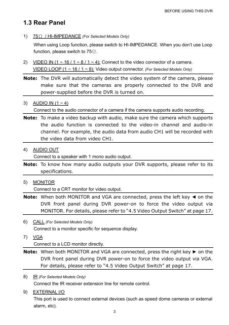
1.3 Rear Panel<br />
1) 75Ω / HI-IMPEDANCE (For Selected Models Only)<br />
When using Loop function, please switch to HI-IMPEDANCE. When you don’t use Loop<br />
function, please switch to 75Ω.<br />
2) VIDEO IN (1 ~ 16 / 1 ~ 8 / 1 ~ 4): Connect to the video connector of a camera.<br />
VIDEO LOOP (1 ~ 16 / 1 ~ 8): Video output connector. (For Selected Models Only)<br />
Note: The <strong>DVR</strong> will automatically detect the video system of the camera, please<br />
make sure that the cameras are properly connected to the <strong>DVR</strong> and<br />
power-supplied before the <strong>DVR</strong> is turned on.<br />
3) AUDIO IN (1 ~ 4)<br />
Connect to the audio connector of a camera if the camera supports audio recording.<br />
Note: To make a video backup with audio, make sure the camera which supports<br />
the audio function is connected to the video-in channel and audio-in<br />
channel. For example, the audio data from audio CH1 will be recorded with<br />
the video data from video CH1.<br />
4) AUDIO OUT<br />
Connect to a speaker with 1 mono audio output.<br />
Note: To know how many audio outputs your <strong>DVR</strong> supports, please refer to its<br />
specifications.<br />
5) MONITOR<br />
Connect to a CRT monitor for video output.<br />
Note: When both MONITOR and VGA are connected, press the left key ◄ on the<br />
<strong>DVR</strong> front panel during <strong>DVR</strong> power-on to force the video output via<br />
MONITOR. For details, please refer to “4.5 Video Output Switch” at page 17.<br />
6) CALL (For Selected Models Only)<br />
Connect to a monitor specific for sequence display.<br />
7) VGA<br />
Connect to a LCD monitor directly.<br />
Note: When both MONITOR and VGA are connected, press the right key ► on the<br />
<strong>DVR</strong> front panel during <strong>DVR</strong> power-on to force the video output via VGA.<br />
For details, please refer to “4.5 Video Output Switch” at page 17.<br />
8) IR (For Selected Models Only)<br />
Connect the IR receiver extension line for remote control.<br />
9) EXTERNAL I/O<br />
This port is used to connect external devices (such as speed dome cameras or external<br />
alarm, etc).<br />
3