Gears, Chains, and Sprockets - VEX Robotics
Gears, Chains, and Sprockets - VEX Robotics
Gears, Chains, and Sprockets - VEX Robotics

You also want an ePaper? Increase the reach of your titles
YUMPU automatically turns print PDFs into web optimized ePapers that Google loves.
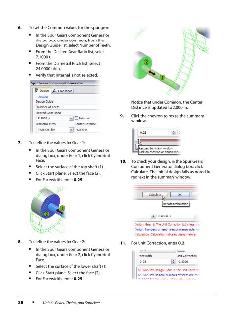
6. To set the Common values for the spur gear:■■■■In the Spur <strong>Gears</strong> Component Generatordialog box, under Common, from theDesign Guide list, select Number of Teeth.From the Desired Gear Ratio list, select7.1000 ul.From the Diametral Pitch list, select24.0000 ul/in.Verify that Internal is not selected.Notice that under Common, the CenterDistance is updated to 2.000 in.9. Click the chevron to resize the summarywindow.7. To define the values for Gear 1:■In the Spur <strong>Gears</strong> Component Generatordialog box, under Gear 1, click CylindricalFace.■Select the surface of the top shaft (1).■Click Start plane. Select the face (2).■For Facewidth, enter 0.25.10. To check your design, in the Spur <strong>Gears</strong>Component Generator dialog box, clickCalculate. The initial design fails as noted inred text in the summary window.8. To define the values for Gear 2:■In the Spur <strong>Gears</strong> Component Generatordialog box, under Gear 2, click CylindricalFace.■Select the surface of the lower shaft (1).11. For Unit Correction, enter 0.2.■Click Start plane. Select the face (2).■For Facewidth, enter 0.25.28■Unit 6: <strong>Gears</strong>, <strong>Chains</strong>, <strong>and</strong> <strong>Sprockets</strong>