January 2012 Capital Investment - National Grid
January 2012 Capital Investment - National Grid
January 2012 Capital Investment - National Grid
You also want an ePaper? Increase the reach of your titles
YUMPU automatically turns print PDFs into web optimized ePapers that Google loves.
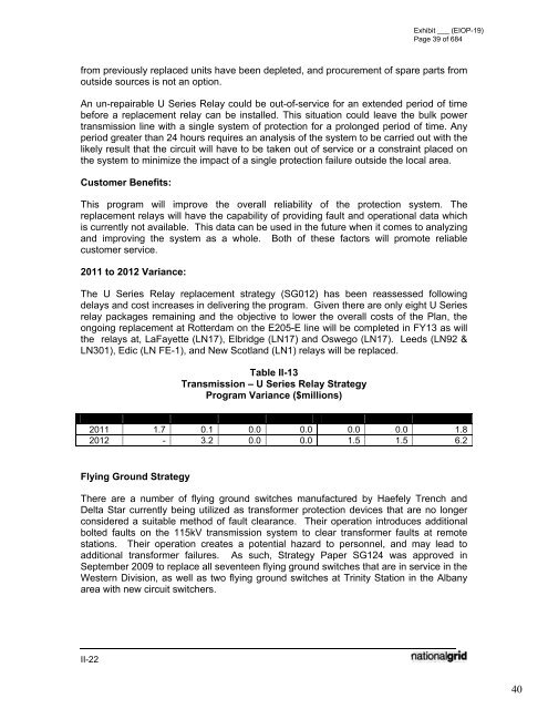
Exhibit ___ (EIOP-19)Page 39 of 684from previously replaced units have been depleted, and procurement of spare parts fromoutside sources is not an option.An un-repairable U Series Relay could be out-of-service for an extended period of timebefore a replacement relay can be installed. This situation could leave the bulk powertransmission line with a single system of protection for a prolonged period of time. Anyperiod greater than 24 hours requires an analysis of the system to be carried out with thelikely result that the circuit will have to be taken out of service or a constraint placed onthe system to minimize the impact of a single protection failure outside the local area.Customer Benefits:This program will improve the overall reliability of the protection system. Thereplacement relays will have the capability of providing fault and operational data whichis currently not available. This data can be used in the future when it comes to analyzingand improving the system as a whole. Both of these factors will promote reliablecustomer service.2011 to <strong>2012</strong> Variance:The U Series Relay replacement strategy (SG012) has been reassessed followingdelays and cost increases in delivering the program. Given there are only eight U Seriesrelay packages remaining and the objective to lower the overall costs of the Plan, theongoing replacement at Rotterdam on the E205-E line will be completed in FY13 as willthe relays at, LaFayette (LN17), Elbridge (LN17) and Oswego (LN17). Leeds (LN92 &LN301), Edic (LN FE-1), and New Scotland (LN1) relays will be replaced.Table II-13Transmission – U Series Relay StrategyProgram Variance ($millions)CIP FY12 FY13 FY14 FY15 FY16 FY17 Total2011 1.7 0.1 0.0 0.0 0.0 0.0 1.8<strong>2012</strong> - 3.2 0.0 0.0 1.5 1.5 6.2Flying Ground StrategyThere are a number of flying ground switches manufactured by Haefely Trench andDelta Star currently being utilized as transformer protection devices that are no longerconsidered a suitable method of fault clearance. Their operation introduces additionalbolted faults on the 115kV transmission system to clear transformer faults at remotestations. Their operation creates a potential hazard to personnel, and may lead toadditional transformer failures. As such, Strategy Paper SG124 was approved inSeptember 2009 to replace all seventeen flying ground switches that are in service in theWestern Division, as well as two flying ground switches at Trinity Station in the Albanyarea with new circuit switchers.II-2240


