SDISC Assembler Call - NetEx
SDISC Assembler Call - NetEx
SDISC Assembler Call - NetEx
- No tags were found...
You also want an ePaper? Increase the reach of your titles
YUMPU automatically turns print PDFs into web optimized ePapers that Google loves.
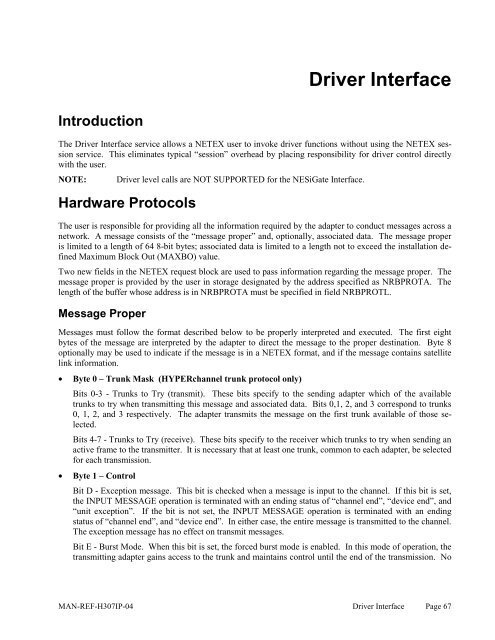
Driver InterfaceIntroductionThe Driver Interface service allows a NETEX user to invoke driver functions without using the NETEX sessionservice. This eliminates typical “session” overhead by placing responsibility for driver control directlywith the user.NOTE: Driver level calls are NOT SUPPORTED for the NESiGate Interface.Hardware ProtocolsThe user is responsible for providing all the information required by the adapter to conduct messages across anetwork. A message consists of the “message proper” and, optionally, associated data. The message properis limited to a length of 64 8-bit bytes; associated data is limited to a length not to exceed the installation definedMaximum Block Out (MAXBO) value.Two new fields in the NETEX request block are used to pass information regarding the message proper. Themessage proper is provided by the user in storage designated by the address specified as NRBPROTA. Thelength of the buffer whose address is in NRBPROTA must be specified in field NRBPROTL.Message ProperMessages must follow the format described below to be properly interpreted and executed. The first eightbytes of the message are interpreted by the adapter to direct the message to the proper destination. Byte 8optionally may be used to indicate if the message is in a NETEX format, and if the message contains satellitelink information.• Byte 0 – Trunk Mask (HYPERchannel trunk protocol only)Bits 0-3 - Trunks to Try (transmit). These bits specify to the sending adapter which of the availabletrunks to try when transmitting this message and associated data. Bits 0,1, 2, and 3 correspond to trunks0, 1, 2, and 3 respectively. The adapter transmits the message on the first trunk available of those selected.Bits 4-7 - Trunks to Try (receive). These bits specify to the receiver which trunks to try when sending anactive frame to the transmitter. It is necessary that at least one trunk, common to each adapter, be selectedfor each transmission.• Byte 1 – ControlBit D - Exception message. This bit is checked when a message is input to the channel. If this bit is set,the INPUT MESSAGE operation is terminated with an ending status of “channel end”, “device end”, and“unit exception”. If the bit is not set, the INPUT MESSAGE operation is terminated with an endingstatus of “channel end”, and “device end”. In either case, the entire message is transmitted to the channel.The exception message has no effect on transmit messages.Bit E - Burst Mode. When this bit is set, the forced burst mode is enabled. In this mode of operation, thetransmitting adapter gains access to the trunk and maintains control until the end of the transmission. NoMAN-REF-H307IP-04 Driver Interface Page 67


