

MY1 Mechanically Jointed Rodless Cylinder
MY1 Mechanically Jointed Rodless Cylinder
MY1 Mechanically Jointed Rodless Cylinder
- No tags were found...

Create successful ePaper yourself
Turn your PDF publications into a flip-book with our unique Google optimized e-Paper software.
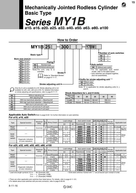
<strong>Mechanically</strong> <strong>Jointed</strong> <strong>Rodless</strong> <strong>Cylinder</strong>Basic TypeSeries <strong>MY1</strong>Bø10, ø16, ø20, ø25, ø32, ø40, ø50, ø63, ø80, ø10015How to Order<strong>MY1</strong>B25300Y7BWNilALHALAHLHBore size (mm)10162025324050638010010 mm16 mm20 mm25 mm32 mm40 mm50 mm63 mm80 mm100 mmBasic typeNilGPipingStandard typeCentralized piping typeNote) For ø10, only G isavailable.Stroke adjusting unitOnly the A unit is available for ø16. Stroke adjusting unit is notavailable for ø50, ø63, ø80 and ø100. For detailed informationon stroke adjusting unit specifications, refer to page 8-11-17.Without adjusting unitWith adjusting boltWith low load shock absorber + Adjusting boltWith high load shock absorber + Adjusting boltWith one A unit and one L unitWith one A unit and one H unit eachWith one L unit and one H unit eachStrokeRefer to “Standard Stroke”on page 8-11-17.Shock Absorbers for L and H UnitsBore size(mm)Unit no.L unitH unit10—RB0805NilS20RB0806RB100725RB1007RB1412Number of auto switchesNilSnAuto switch21nNil Without auto switch∗ For the applicable auto switchmodel, refer to the table below.∗ Auto switches are shipped together,(but not assembled).Suffix for stroke adjusting unit Note)Both sidesOne sideNote) “S” is applicable for stroke adjusting units A, Land H.32 40RB1412RB2015Applicable Auto Switch/Refer to page 8-30-1 for further information on auto switches.For ø10, ø16, ø20TypeReedswitchSolidstateswitchSpecial functionDiagnostic indication(2-color indication)ElectricalentryGrommetGrommetIndicatorlightYesYesFor ø25, ø32, ø40, ø50, ø63, ø80, ø100TypeReedswitchSolidstateswitch—Special functionDiagnostic indication(2-color indication)ElectricalentryGrommetGrommetYesYes∗ Lead wire length symbols: 0.5 m·······Nil (Example) A933 m········L (Example) Y59BL5 m········Z (Example) F9NWZWiring (Output)3-wire (NPN equivalent)2-wire3-wire (NPN)3-wire (PNP)2-wire3-wire (NPN)3-wire (PNP)2-wire• There are other applicable auto switches than listed above. For details, refer to page 8-11-101.• For details about auto switches with pre-wire connector, refer to page 8-30-52.8-11-16———IndicatorlightLoad voltage Auto switch model Lead wire length (m) ∗Pre-wire0.5 3 5DC AC Perpendicular In-lineconnector(Nil) (L) (Z)Applicable load— 5 V — A96V A96 — — IC circuit —24 V 12 V 100 V A93V A93 — — — Relay, PLCM9NV M9N 5 V, 12 VIC circuitM9PV M9P Relay12 VM9BV M9B —24 V —PLCF9NWV F9NW 5 V, 12 VIC circuitF9PWV F9PW 12 V F9BWV F9BW —Load voltage Auto switch model Lead wire length (m) ∗Wiring (Output)Pre-wire0.5 3 5Applicable loadDC AC Perpendicular In-lineconnector(Nil) (L) (Z)3-wire (NPN equivalent) — 5 V — — Z76 — — IC circuit —2-wire 24 V 12 V 100 V — Z73 — — Relay, PLC3-wire (NPN)Y69A Y59A 5 V, 12 VIC circuit3-wire (PNP)Y7PV Y7P 2-wire12 VY69B Y59B — Relay24 V —PLC3-wire (NPN)Y7NWV Y7NW 5 V, 12 VIC circuit3-wire (PNP)Y7PWV Y7PW 2-wire12 V Y7BWV Y7BW —∗ Solid state switches marked with “” are produced upon receipt of order.


