

MY1 Mechanically Jointed Rodless Cylinder
MY1 Mechanically Jointed Rodless Cylinder
MY1 Mechanically Jointed Rodless Cylinder
- No tags were found...

Create successful ePaper yourself
Turn your PDF publications into a flip-book with our unique Google optimized e-Paper software.
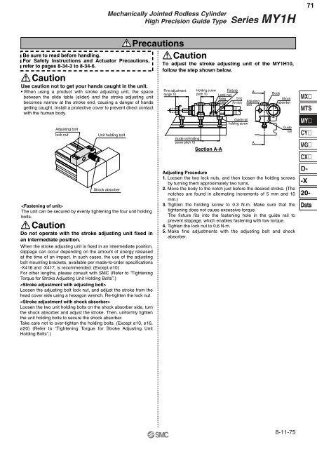
<strong>Mechanically</strong> <strong>Jointed</strong> <strong>Rodless</strong> <strong>Cylinder</strong>High Precision Guide TypeSeries <strong>MY1</strong>H71Be sure to read before handling.For Safety Instructions and Actuator Precautions,refer to pages 8-34-3 to 8-34-6.CautionUse caution not to get your hands caught in the unit.• When using a product with stroke adjusting unit, the spacebetween the slide table (slider) and the stroke adjusting unitbecomes narrow at the stroke end, causing a danger of handsgetting caught. Install a protective cover to prevent direct contactwith the human body.Adjusting boltlock nutUnit holding boltShock absorberThe unit can be secured by evenly tightening the four unit holdingbolts.CautionDo not operate with the stroke adjusting unit fixed inan intermediate position.When the stroke adjusting unit is fixed in an intermediate position,slippage can occur depending on the amount of energy releasedat the time of an impact. In such cases, the use of the adjustingbolt mounting brackets, available per made-to-order specifications-X416 and -X417, is recommended. (Except ø10)For other lengths, please consult with SMC (Refer to “TighteningTorque for Stroke Adjusting Unit Holding Bolts”.)Loosen the adjusting bolt lock nut, and adjust the stroke from thehead cover side using a hexagon wrench. Re-tighten the lock nut.Loosen the two unit holding bolts on the shock absorber side, turnthe shock absorber and adjust the stroke. Then, uniformly tightenthe unit holding bolts to secure the shock absorber.Take care not to over-tighten the holding bolts. (Except ø10, ø16,ø20) (Refer to “Tightening Torgue for Stroke Adjusting UnitHolding Bolts”.)PrecautionsCautionTo adjust the stroke adjusting unit of the <strong>MY1</strong>H10,follow the step shown below.Fine adjustmentrange 10Guide rail holdingscrew pitch 15Holding screwpitch 10Section A-AFixtureLock nutFixingscrewO-ring(For notch)Guide railholding screwAdjustingboltBodyShockabsorberGuiderailAdjusting Procedure1. Loosen the two lock nuts, and then loosen the holding screwsby turning them approximately two turns.2. Move the body to the notch just before the desired stroke. (Thenotches are found in alternating increments of 5 mm and 10mm.)3. Tighten the holding screw to 0.3 N·m. Make sure that thetightening does not cause excessive torque.The fixture fits into the fastening hole in the guide rail toprevent slippage, which enables fastening with low torque.4. Tighten the lock nut to 0.6 N·m.5. Make fine adjustments with the adjusting bolt and shockabsorber.AAMXMTSMYCYMGCXD--X20-Data8-11-75


