

MY1 Mechanically Jointed Rodless Cylinder
MY1 Mechanically Jointed Rodless Cylinder
MY1 Mechanically Jointed Rodless Cylinder
- No tags were found...

Create successful ePaper yourself
Turn your PDF publications into a flip-book with our unique Google optimized e-Paper software.
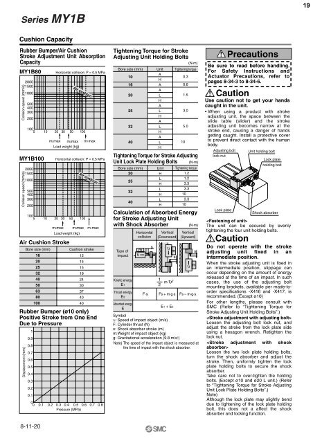
Series <strong>MY1</strong>B19Cushion CapacityRubber Bumper/Air CushionStroke Adjustment Unit AbsorptionCapacity<strong>MY1</strong>B80Collision speed (mm/s)200015001000<strong>MY1</strong>B100Collision speed (mm/s)200015001000Displacement (mm)500400300200100 5 10 20 30 50 100500400300200Horizontal collision: P = 0.5 MPam2max m3max m1maxLoad weight (kg)Horizontal collision: P = 0.5 MPa100 5 10 20 30 50 100m2max m3max m1maxLoad weight (kg)Air Cushion StrokeBore size (mm)162025324050638010010.90.80.70.60.50.40.30.20.1Air cushionAir cushionCushion stroke121515192430374040Rubber Bumper (ø10 only)Positive Stroke from One EndDue to Pressure00 0.1 0.2 0.3 0.4 0.5 0.6 0.7 0.8Pressure (MPa)8-11-20Tightening Torque for StrokeAdjusting Unit Holding Bolts(N·m)Bore size (mm)101620253240UnitAHAALHALHALHALHTightening torqueTightening Torque for Stroke AdjustingUnit Lock Plate Holding Bolts (N·m)Bore size (mm)20253240UnitHLHLHLHTightening torque1.21.23.33.3103.310Calculation of Absorbed Energyfor Stroke Adjusting Unitwith Shock Absorber(N·m)Type ofimpactKinetic energyE1Thrust energyE2Absorbed energyEHorizontalcollisionυ msVertical(Downward)12υ mm·υ 2Vertical(Upward)F·s Fs + m·g·s Fs – m·g·sE1 + E2s0.30.61.53.05.0sυ mSymbolυ: Speed of impact object (m/s)F: <strong>Cylinder</strong> thrust (N)s: Shock absorber stroke (m)m:Weight of impact object (kg)g: Gravitational acceleration (9.8 m/s 2 )Note) The speed of the impact object is measured atthe time of impact with the shock absorber.10PrecautionsBe sure to read before handling.For Safety Instructions andActuator Precautions, refer topages 8-34-3 to 8-34-6.CautionUse caution not to get your handscaught in the unit.• When using a product with strokeadjusting unit, the space between theslide table (slider) and the strokeadjusting unit becomes narrow at thestroke end, causing a danger of handsgetting caught. Install a protective coverto prevent direct contact with the humanbody.Adjusting boltlock nutLock plateThe unit can be secured by evenlytightening the four unit holding bolts.CautionUnit holding boltLock plateholding boltShock absorberDo not operate with the strokeadjusting unit fixed in anintermediate position.When the stroke adjusting unit is fixed inan intermediate position, slippage canoccur depending on the amount of energyreleased at the time of an impact. In suchcases, the use of the adjusting boltmounting brackets, available per made-toorderspecifications -X416 and -X417, isrecommended. (Except ø10)For other lengths, please consult withSMC (Refer to “Tightening Torque forStroke Adjusting Unit Holding Bolts”.)Loosen the adjusting bolt lock nut, andadjust the stroke from the lock plate sideusing a hexagon wrench. Retighten thelock nut.Loosen the two lock plate holding bolts,turn the shock absorber and adjust thestroke. Then, uniformly tighten the lockplate holding bolts to secure the shockabsorber.Take care not to over-tighten the holdingbolts. (Except ø10 and ø20 L unit.) (Referto “Tightening Torque for Stroke AdjustingUnit Lock Plate Holding Bolts”.)Note)Although the lock plate may slightly benddue to tightening of the lock plate holdingbolt, this does not a affect the shockabsorber and locking function.


