

MY1 Mechanically Jointed Rodless Cylinder
MY1 Mechanically Jointed Rodless Cylinder
MY1 Mechanically Jointed Rodless Cylinder
- No tags were found...

Create successful ePaper yourself
Turn your PDF publications into a flip-book with our unique Google optimized e-Paper software.
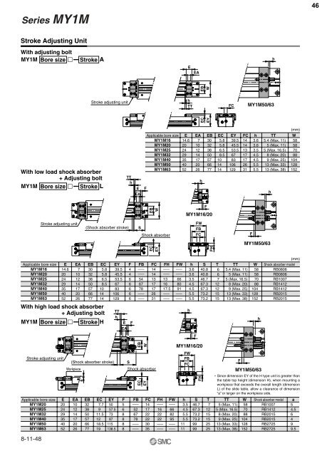
Series <strong>MY1</strong>M46Stroke Adjusting UnitWith adjusting bolt<strong>MY1</strong>M Bore size Stroke AEEAhEBWStroke adjusting unithTTFC<strong>MY1</strong>M50/63ECEYWith low load shock absorber+ Adjusting bolt<strong>MY1</strong>M Bore size Stroke LTThEEAApplicable bore size E EA EB EC EY FC h TT<strong>MY1</strong>M16<strong>MY1</strong>M2014.62071030325.85.839.545.514143.63.6<strong>MY1</strong>M25 24 12 38 6.5 53.5 13 3.5<strong>MY1</strong>M32 29 14 50 8.5 67 17 4.5F<strong>MY1</strong>M40<strong>MY1</strong>M50<strong>MY1</strong>M6335 17 57 10 83 17 4.540 20 66 14 106 26 5.552 26 77 14 129 31 5.5h5.4 (Max. 11)5 (Max. 11)5 (Max. 16.5)8 (Max. 20)9 (Max. 25)13 (Max. 33)13 (Max. 38)h(mm)W58587088104128152EBWF<strong>MY1</strong>M16/20Stroke adjusting unit(Shock absorber stroke)SShock absorberFWFBFCF<strong>MY1</strong>M50/63ECEYFHApplicable bore size<strong>MY1</strong>M16<strong>MY1</strong>M20<strong>MY1</strong>M25<strong>MY1</strong>M32<strong>MY1</strong>M40<strong>MY1</strong>M50<strong>MY1</strong>M63With high load shock absorber+ Adjusting bolt<strong>MY1</strong>M Bore size Stroke HStroke adjusting unitApplicable bore size<strong>MY1</strong>M20<strong>MY1</strong>M25<strong>MY1</strong>M32<strong>MY1</strong>M40<strong>MY1</strong>M50<strong>MY1</strong>M638-11-48(mm)E EA EB EC EY F FB FC FH FW h S T TT W Shock absorber model14.6 7 304 ––– 14 ––– ––– 3.6 40.8 6 5.4 (Max. 11) 58 RB080620 10 324 ––– 14 ––– ––– 3.6 40.8 6 5 (Max. 11) 58 RB080624 12 386 54 13 13 66 3.5 46.7 7 5 (Max. 16.5) 70 RB100729 14 506 67 17 16 80 4.5 67.3 12 8 (Max. 20) 88 RB141235 17 576 78 17 17.5 91 4.5 67.3 12 9 (Max. 25) 104 RB14124052202666775.85.86.58.510141439.545.553.56783106129E EA EB EC EY F FB FC FH FW h S T TT W Shock absorber model a20 10 325 ––– 14 ––– ––– 46.7 7 5 (Max. 11) 58 RB1007 524 12 386 52 17 16 66 67.3 12 5 (Max. 16.5) 70 RB1412 4.529 14 508 67 22 22 82 73.2 15 8 (Max. 20) 88 RB2015 635 17 578 78 22 22 95 73.2 15 9 (Max. 25) 104 RB2015 44052(Shock absorber stroke)Workpiece2026a66777.7911.51218.5195057.57387115138.5TThEEA8866F––––––––––––EBW30352631SShock absorberECEY––––––––––––––––––––––––3.54.55.55.511115.55.5h<strong>MY1</strong>M16/20FWFBFCF9999FH73.273.22525151513 (Max. 33)13 (Max. 38)13 (Max. 33)13 (Max. 38)F128152128152<strong>MY1</strong>M50/63RB2725RB2725RB2015RB2015∗ Since dimension EY of the H type unit is greater thanthe table top height (dimension H), when mounting aworkpiece that exceeds the overall length (dimensionL) of the slide table, allow a clearance of dimension“a” or larger on the workpiece side.h99.5


