

MY1 Mechanically Jointed Rodless Cylinder
MY1 Mechanically Jointed Rodless Cylinder
MY1 Mechanically Jointed Rodless Cylinder
- No tags were found...

You also want an ePaper? Increase the reach of your titles
YUMPU automatically turns print PDFs into web optimized ePapers that Google loves.
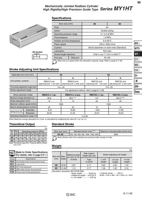
<strong>Mechanically</strong> <strong>Jointed</strong> <strong>Rodless</strong> <strong>Cylinder</strong>High Rigidity/High Precision Guide TypeSeries <strong>MY1</strong>HT90SpecificationsJIS SymbolStroke Adjusting Unit SpecificationsApplicable bore size (mm)Unit symbol, contentsFine stroke adjustment range (mm)Stroke adjustment rangeShock absorber modelMaximum energy absorption (J)Stroke absorption (mm)Maximum collision speed (mm/s)Maximum operating frequency (cycle/min)Spring force (N)ExtendedRetractedOperating temperature range (°C)LRB2015 andadjusting bolt: 1 set eachFluidActionOperating pressure rangeProof pressureAmbient and fluid temperaturePiston speedCushionLubricationStroke length tolerancePort size Side port50 63AirDouble acting0.1 to 0.8 MPa1.2 MPa5 to 60°C100 to 1000 mm/sShock absorbers on both ends (Standard)Non-lubeRc 3/8Note) Use at a speed within the absorption capacity range. Refer to page 8-11-96.50 63HRB2015 andadjusting bolt: 2 sets eachLRB2725 andadjusting bolt: 1 set each0 to –20 0 to –25For adjustment method, refer to page 8-11-96.HRB2725 andadjusting bolt: 2 sets eachRB2015 x 1 pc. RB2015 x 2 pcs. RB2725 x 1 pc. RB2725 x 2 pcs.58.815258.3420.50Bore size (mm)88.2 Note)1525147251000 100016.6841.005 to 60Note) Maximum energy absorption for 2 pcs. is calculated by multiplying the value for 1 pc. by 1.5.+1.8+2.82700 or less 0 , 2701 to 5000 0108.8320.01220.5 Note)251017.6640.02MXMTSMYCYMGCXD--X20-DataTheoretical OutputBoresize(mm)5063(N)Piston Operating pressure (MPa)area(mm 2 ) 0.2 0.3 0.4 0.5 0.6 0.7 0.81962 392 588 784 981 1177 1373 15693115 623 934 1246 1557 1869 2180 2492Note) Theoretical output (N) = Pressure (MPa) x Pistonarea (mm 2 )Standard StrokeBore size (mm) Standard stroke (mm) Note)Maximum manufacturable stroke (mm)50, 63 200, 400, 600, 800, 1000, 1500, 2000 5000Note) Strokes other than standard are produced after receipt of order.WeightMade to Order Specifications(For details, refer to page 8-31-1.)SymbolSpecifications-XB10 Intermediate stroke (Using exclusive body)-XB11 Long stroke-XC18 NPT finish piping port-XC67 NBR rubber lining in dust seal band-X168 Helical insert thread specificationsBore size(mm)BasicweightAdditional weightper each 25 mmof strokeSide supportweight (per set)TypeA and B506330.6241.690.871.130.170.17Calculation: (Example) <strong>MY1</strong>HT50-400L• Basic weight ·············30.62 kg• Additional weight ····0.87/25 st• L unit weight ···············0.62 kgStroke adjusting unit weightL unitweight0.621.08LH unitweight0.931.62H unitweight1.242.16(kg)• <strong>Cylinder</strong> stroke········· 400 st30.62 + 0.87 x 400 ÷ 25 + 0.62 x 2 ≅ 45.88-11-95


