

MY1 Mechanically Jointed Rodless Cylinder
MY1 Mechanically Jointed Rodless Cylinder
MY1 Mechanically Jointed Rodless Cylinder
- No tags were found...

You also want an ePaper? Increase the reach of your titles
YUMPU automatically turns print PDFs into web optimized ePapers that Google loves.
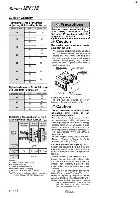
Series <strong>MY1</strong>M42Cushion CapacityTightening Torque for StrokeAdjusting Unit Holding Bolts (N·m)Bore size (mm)Calculation of Absorbed Energy for StrokeAdjusting Unit with Shock AbsorberType ofimpact16202532405063Kinetic energyE1Thrust energyE2Absorbed energyEHorizontalcollisionF·SUnitALALHALHALHALHALHALHVertical(Downward)1–– mυ22Vertical(Upward)F·S + m·g·s F·S – m·g·sE1 + E2Tightening torqueTightening Torque for Stroke AdjustingUnit Lock Plate Holding BoltsBore size (mm)253240υ msUnitLHLHLH(N·m)Tightening torque1.23.33.3103.310υ m(N·m)Symbolυ: Speed of impact object (m/s)F: <strong>Cylinder</strong> thrust (N)s: Shock absorber stroke (m)m: Weight of impact object (kg)g: Gravitational acceleration (9.8 m/s 2 )Note) The speed of the impact object is measured atthe time of impact with the shock absorber.8-11-44s0.61.53.05.05.012121224sυ mPrecautionsBe sure to read before handling.For Safety Instructions andActuator Precautions, refer topages 8-34-3 to 8-34-6.CautionUse caution not to get your handscaught in the unit.• When using a product with stroke adjustingunit, the space between the slide table(slider) and the stroke adjusting unitbecomes narrow at the stroke end, causinga danger of hands getting caught. Install aprotective cover to prevent direct contactwith the human body.Adjusting boltLock nutLock plateShock absorberThe unit can be secured by evenlytightening the four unit holding bolts.CautionUnit holding boltLock plateholding boltDo not operate with the strokeadjusting unit fixed in anintermediate position.When the stroke adjusting unit is fixed inan intermediate position, slippage canoccur depending on the amount of energyreleased at the time of an impact. In suchcases, the use of the adjusting boltmounting brackets, available per made-toorderspecifications -X416 and -X417, isrecommended.For other lengths, please consult with SMC(Refer to “Tightening Torque for StrokeAdjusting Unit Holding Bolts”.)Loosen the adjusting bolt lock nut, andadjust the stroke from the lock plate sideusing a hexagon wrench. Retighten thelock nut.Loosen the two lock plate holding bolts,turn the shock absorber and adjust thestroke. Then, uniformly tighten the lockplate holding bolts to secure the shockabsorber.Take care not to over-tighten the holdingbolts. (Except ø16, ø20, ø50, ø63)(Refer to “Tightening Torgue for StrokeAdjusting Unit Lock Plate Holding Bolts”.)Note) Although the lock plate may slightly benddue to tightening of the lock plate holdingbolt, this does not a affect the shockabsorber and locking function.


