

MY1 Mechanically Jointed Rodless Cylinder
MY1 Mechanically Jointed Rodless Cylinder
MY1 Mechanically Jointed Rodless Cylinder
- No tags were found...

Create successful ePaper yourself
Turn your PDF publications into a flip-book with our unique Google optimized e-Paper software.
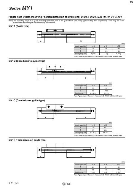
Series <strong>MY1</strong>99Proper Auto Switch Mounting Position (Detection at stroke end) D-M9, D-M9V, D-F9W, D-F9WVNote) The operating range is a guide including hysteresis, but is not guaranteed. (assuming approximately 30% dispersion.) There may be variedsubstantially depending on the surrounding environment.<strong>MY1</strong>B (Basic type)AB(mm)Mounting position ø10 ø16 ø20ABOperating range l Note)24863 (2.5)311294 (3)391615 (3.5)Note) Figures in parentheses are the cases for D-M9, D-M9V switch types.<strong>MY1</strong>M (Slide bearing guide type)AB(mm)Mounting position ø16ø20ABOperating range l Note)74868.5 (6.5)941066.5 (7)Note) Figures in parentheses are the cases for D-M9, D-M9V switch types.<strong>MY1</strong>C (Cam follower guide type)AB(mm)Mounting position ø16ø20ABOperating range l Note)74868.5 (6.5)941066.5 (7)Note) Figures in parentheses are the cases for D-M9, D-M9V switch types.<strong>MY1</strong>H (High precision guide type)AB(mm)Mounting position ø10 ø16 ø20ABOperating range l Note)24863 (2)311294 (3)391615 (3.5)Note) Figures in parentheses are the cases for D-M9, D-M9V switch types.8-11-104


