

MY1 Mechanically Jointed Rodless Cylinder
MY1 Mechanically Jointed Rodless Cylinder
MY1 Mechanically Jointed Rodless Cylinder
- No tags were found...

Create successful ePaper yourself
Turn your PDF publications into a flip-book with our unique Google optimized e-Paper software.
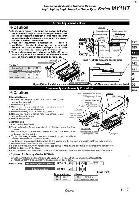
<strong>Mechanically</strong> <strong>Jointed</strong> <strong>Rodless</strong> <strong>Cylinder</strong>High Rigidity/High Precision Guide TypeSeries <strong>MY1</strong>HT92Caution1. As shown in Figure (1), to adjust the stopper bolt withinthe adjustment range A, insert a hexagon wrench fromthe top to loosen the hexagon socket head set screwby approximately one turn, and then adjust the stopperbolt with a flat head screwdriver.2. When the adjustment described in 1 above isinsufficient, the shock absorber can be adjusted.Remove the covers as shown in Figure (2) and makefurther adjustment by loosening the hexagon nut.3. Various dimensions are indicated in Table (1). Nevermake an adjustment that exceeds the dimensions in thetable, as it may cause an accident and/or damage.Table (1)Bore size (mm)A to A MAXB to B MAXCMax. adjustment rangeCaution50 636 to 2614 to 5487606 to 3114 to 7410285Top coverHexagon socket head cap screwDisassembly step1. Remove the hexagon socket head cap screws 1, andremove the upper plates.2. Remove the top cover.3. Remove the hexagon socket head cap screws 2, andremove the end covers and couplers.4. Remove the hexagon socket head cap screws 3.5. Remove the hexagon socket head cap screws 4, andremove the end supports.6. Remove the cylinder.∗ <strong>Cylinder</strong> For Driving (Series <strong>MY1</strong>BH)Stroke Adjustment MethodFigure (2) Cover installation and removalDisassembly and Assembly ProcedureHexagon socket head cap screw 1(Tightening torque 25 N·m)Upper plateHexagon socket headcap screw 4(ø50: Tightening torque 5 N·mCoupler ø63: Tightening torque 11 N·m)End coverHexagon sockethead cap screw 2(Tightening torque 25 N·m)Assembly step1. Insert the <strong>MY1</strong>BH cylinder.2. Temporarily fasten the end supports with the hexagon socket head capscrews 4.3. With two hexagon socket head cap screws 3 on the L or R side, pull theend support and the cylinder.4. Tighten the hexagon socket head cap screws 3 on the other side toeliminate the looseness in the axial direction.Upper plate ass'ySide coverHexagon socket button head screwEnd support<strong>Cylinder</strong> ∗for driving(<strong>MY1</strong>BH)Hexagon socket head cap screw 3(Tightening torque 3 N·m)Since Series <strong>MY1</strong>BH is a cylinder for driving for Series <strong>MY1</strong>HT, its construction is different from Series <strong>MY1</strong>B.Do not use Series <strong>MY1</strong>B as a cylinder for driving, since it will lead to damage.How to Order High rigidity/High precision guide type <strong>MY1</strong>HT 50 300 L Z73Stopper boltA(Stopper bolt side)Hexagon wrenchTorqueAdjuster holderM16 x 2Flat head screwdriverTop coverLB(Shock absorber side)Shock absorberHexagon nutAbsorber ring10 (Ring width)Figure (1) Stroke adjusting section detailAMAXC (Stopper bolt overall length)BMAXFigure (3) Maximum stroke adjustment detail(At this point, a space is created between the end support and the end plate on one side, but this is not a problem.)5. Re-tighten the hexagon socket head cap screws 4.6. Fasten the end cover with the hexagon head cap screws 2, while making sure that the coupler is in the right direction.7. Place the top cover on the body.8. Insert the holding blocks into the top cover and fasten the upper plates with the hexagon socket head cap screws 1.Holding blockEnd plateRMXMTSMYCYMGCXD--X20-Data<strong>Cylinder</strong> for driving<strong>MY1</strong>BH 50 300Bore size (mm)506350 mm63 mmPipingNilGStandard typeCentralized piping typeStroke (mm)8-11-97


