

MY1 Mechanically Jointed Rodless Cylinder
MY1 Mechanically Jointed Rodless Cylinder
MY1 Mechanically Jointed Rodless Cylinder
- No tags were found...

You also want an ePaper? Increase the reach of your titles
YUMPU automatically turns print PDFs into web optimized ePapers that Google loves.
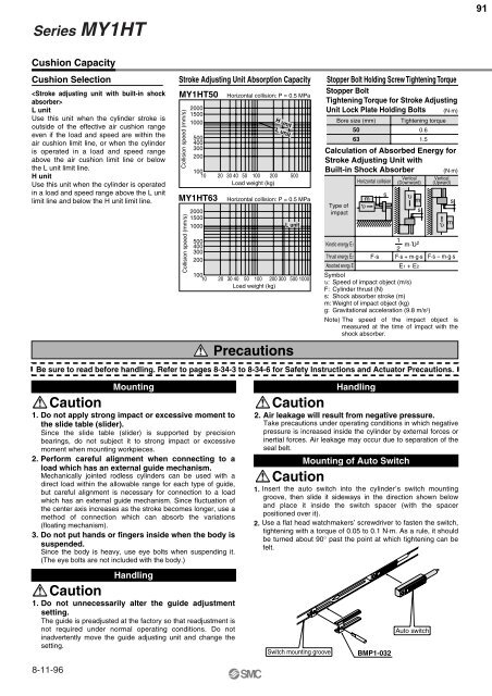
Series <strong>MY1</strong>HT91Cushion CapacityCushion SelectionL unitUse this unit when the cylinder stroke isoutside of the effective air cushion rangeeven if the load and speed are within theair cushion limit line, or when the cylinderis operated in a load and speed rangeabove the air cushion limit line or belowthe L unit limit line.H unitUse this unit when the cylinder is operatedin a load and speed range above the L unitlimit line and below the H unit limit line.Stroke Adjusting Unit Absorption Capacity<strong>MY1</strong>HT50Collision speed (mm/s)20001500100050040030020010010 20 30 40 50 100 200 500Load weight (kg)<strong>MY1</strong>HT63Collision speed (mm/s)200015001000500400300200Horizontal collision: P = 0.5 MPa10010 20 30 40 50 100 200 300 500 1000Load weight (kg)PrecautionsCalculation of Absorbed Energy forStroke Adjusting Unit withBuilt-in Shock AbsorberHorizontal collisionBe sure to read before handling. Refer to pages 8-34-3 to 8-34-6 for Safety Instructions and Actuator Precautions.H unitL unitHorizontal collision: P = 0.5 MPaL unitStopper Bolt Holding Screw Tightening TorqueStopper BoltTightening Torque for Stroke AdjustingUnit Lock Plate Holding Bolts (N·m)Bore size (mm)Type ofimpact5063υ msTightening torque0.61.5Vertical(Downward)υ m(N·m)Kinetic energy E112m·υ 2Thrust energy E2 F·s F·s + m·g·s F·s – m·g·sAbsorbed energy EE1 + E2Symbolυ: Speed of impact object (m/s)F: <strong>Cylinder</strong> thrust (N)s: Shock absorber stroke (m)m: Weight of impact object (kg)g: Gravitational acceleration (9.8 m/s 2 )Note) The speed of the impact object ismeasured at the time of impact with theshock absorber.sVertical(Upward)sυ mCaution1. Do not apply strong impact or excessive moment tothe slide table (slider).Since the slide table (slider) is supported by precisionbearings, do not subject it to strong impact or excessivemoment when mounting workpieces.2. Perform careful alignment when connecting to aload which has an external guide mechanism.<strong>Mechanically</strong> jointed rodless cylinders can be used with adirect load within the allowable range for each type of guide,but careful alignment is necessary for connection to a loadwhich has an external guide mechanism. Since fluctuation ofthe center axis increases as the stroke becomes longer, use amethod of connection which can absorb the variations(floating mechanism).3. Do not put hands or fingers inside when the body issuspended.Since the body is heavy, use eye bolts when suspending it.(The eye bolts are not included with the body.)CautionMountingHandling1. Do not unnecessarily alter the guide adjustmentsetting.The guide is preadjusted at the factory so that readjustment isnot required under normal operating conditions. Do notinadvertently move the guide adjusting unit and change thesetting.Caution2. Air leakage will result from negative pressure.Take precautions under operating conditions in which negativepressure is increased inside the cylinder by external forces orinertial forces. Air leakage may occur due to separation of theseal belt.CautionSwitch mounting grooveHandlingMounting of Auto Switch1. Insert the auto switch into the cylinder , s switch mountinggroove, then slide it sideways in the direction shown belowand place it inside the switch spacer (with the spacerpositioned over it).2. Use a flat head watchmakers’ screwdriver to fasten the switch,tightening with a torque of 0.05 to 0.1 N·m. As a rule, it shouldbe turned about 90° past the point at which tightening can befelt.BMP1-032Auto switch8-11-96


