

MY1 Mechanically Jointed Rodless Cylinder
MY1 Mechanically Jointed Rodless Cylinder
MY1 Mechanically Jointed Rodless Cylinder
- No tags were found...

Create successful ePaper yourself
Turn your PDF publications into a flip-book with our unique Google optimized e-Paper software.
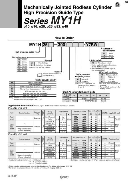
<strong>Mechanically</strong> <strong>Jointed</strong> <strong>Rodless</strong> <strong>Cylinder</strong>High Precision Guide TypeSeries <strong>MY1</strong>Hø10, ø16, ø20, ø25, ø32, ø4068NilALHALAHLHHigh precision guide typeBore size (mm)10162025324010 mm16 mm20 mm25 mm32 mm40 mmNilGPipingStandard typeCentralized piping typeStrokeRefer to “Standard Stroke”on page 8-11-73.Stroke adjusting unitWithout adjusting unitWith adjusting boltWith low load shock absorber + Adjusting boltWith high load shock absorber + Adjusting boltWith one A unit and one L unitWith one A unit and one H unit eachWith one L unit and one H unit eachNote) <strong>MY1</strong>H16 is not available with H unit.<strong>MY1</strong>H10 is not available with A and L units.How to Order<strong>MY1</strong>H 25 300Note) For ø10, only G is available.L unitH unitSuffix for strokeadjusting unit Note)NilSBoth endsOne endShock Absorbers for L and H UnitsBore size(mm)Unit type10—RB08051620RB0806— RB1007Y7BWNote) “S” is applicable forstroke adjusting units A,L and H.Auto switchNumber ofauto switchesNilSn2 pcs1 pcs“n” pcsNil Without auto switch∗ For the applicable auto switch model,refer to the table below.∗ Auto switches are shipped together,(but not assembled)End lock position25RB1007RB1412NilEFW32 40RB1412RB2015Without end lockRight endLeft endBoth ends∗ <strong>MY1</strong>H10 is not available withend lock.∗ For end lock positions, referto page 8-11-83.Applicable Auto Switch/Refer to page 8-30-1 for further information on auto switches.For ø10, ø16, ø20TypeReedswitchSolidstateswitchSpecial functionDiagnostic indication(2-color indication)For ø25, ø32, ø40TypeReedswitchSolidstateswitch——Special function——Diagnostic indication(2-color indication)ElectricalentryGrommetGrommetElectricalentryGrommetGrommetYesYes∗ Lead wire length symbols: 0.5 m····Nil (Example) A933 m·····L (Example) Y59BL5 m·····Z (Example) F9NWZWiring(Output)3-wire (NPN equivalent)2-wire3-wire (NPN)3-wire (PNP)2-wire3-wire (NPN)3-wire (PNP)2-wireWiring(Output)3-wire (NPN equivalent)2-wire3-wire (NPN)3-wire (PNP)2-wire3-wire (NPN)3-wire (PNP)2-wireLoad voltageDC— 5 V —24 V 12 V 100 V5 V, 12 V12 V24 V5 V, 12 V• There are other applicable auto switches than listed above. For details, refer to page 8-11-101.• For details about auto switches with pre-wire connector, refer to page 8-30-52.IndicatorlightIndicatorlightYesYes12 VLoad voltageDC5 V, 12 V12 V24 V5 V, 12 VAC— 5 V —24 V 12 V 100 V12 V—AC—Auto switch modelPerpendicularA96VA93VM9NVM9PVM9BVF9NWVF9PWVF9BWVIn-lineA96A93M9NM9PM9BF9NWF9PWF9BWAuto switch modelPerpendicularIn-lineLead wire length (m) ∗0.5(Nil)0.5(Nil)3(L)3(L)5(Z)——Lead wire length (m) ∗5(Z)Pre-wireconnector——Pre-wireconnectorApplicable loadIC circuit —— Relay, PLCIC circuitIC circuitRelay,PLCApplicable load— Z76 — — IC circuit —— Z73 — — Relay, PLCY69A Y59A IC circuitY7PV Y7P Y69B Y59B —Relay,PLCY7NWV Y7NW IC circuitY7PWV Y7PW Y7BWV Y7BW —∗ Solid state switches marked with “” are produced upon receipt of order.——8-11-72


