

MY1 Mechanically Jointed Rodless Cylinder
MY1 Mechanically Jointed Rodless Cylinder
MY1 Mechanically Jointed Rodless Cylinder
- No tags were found...

Create successful ePaper yourself
Turn your PDF publications into a flip-book with our unique Google optimized e-Paper software.
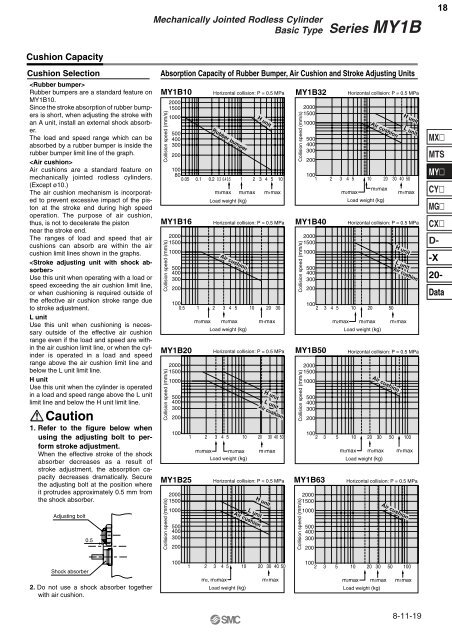
<strong>Mechanically</strong> <strong>Jointed</strong> <strong>Rodless</strong> <strong>Cylinder</strong>Basic TypeSeries <strong>MY1</strong>B18Cushion CapacityCushion SelectionRubber bumpers are a standard feature on<strong>MY1</strong>B10.Since the stroke absorption of rubber bumpersis short, when adjusting the stroke withan A unit, install an external shock absorber.The load and speed range which can beabsorbed by a rubber bumper is inside therubber bumper limit line of the graph.Air cushions are a standard feature onmechanically jointed rodless cylinders.(Except ø10.)The air cushion mechanism is incorporatedto prevent excessive impact of the pistonat the stroke end during high speedoperation. The purpose of air cushion,thus, is not to decelerate the pistonnear the stroke end.The ranges of load and speed that aircushions can absorb are within the aircushion limit lines shown in the graphs.Use this unit when operating with a load orspeed exceeding the air cushion limit line,or when cushioning is required outside ofthe effective air cushion stroke range dueto stroke adjustment.L unitUse this unit when cushioning is necessaryoutside of the effective air cushionrange even if the load and speed are withinthe air cushion limit line, or when the cylinderis operated in a load and speedrange above the air cushion limit line andbelow the L unit limit line.H unitUse this unit when the cylinder is operatedin a load and speed range above the L unitlimit line and below the H unit limit line.Caution1. Refer to the figure below whenusing the adjusting bolt to performstroke adjustment.When the effective stroke of the shockabsorber decreases as a result ofstroke adjustment, the absorption capacitydecreases dramatically. Securethe adjusting bolt at the position whereit protrudes approximately 0.5 mm fromthe shock absorber.Adjusting bolt0.5Absorption Capacity of Rubber Bumper, Air Cushion and Stroke Adjusting Units<strong>MY1</strong>B10Collision speed (mm/s) Collision speed (mm/s)<strong>MY1</strong>B20Collision speed (mm/s)200015001000500400300200100<strong>MY1</strong>B25Collision speed (mm/s)200015001000500400300200200015001000500400300200Horizontal collision: P = 0.5 MPa100800.05 0.1 0.2 0.3 0.4 0.5 1 2 3 4 5 10m3max m2max m1maxLoad weight (kg)Horizontal collision: P = 0.5 MPa2000150010005004003002001000.5<strong>MY1</strong>B161 2 3 4 5 10 20 30m3maxRubber bumperAir cushionm2maxLoad weight (kg)Horizontal collision: P = 0.5 MPa1 2 3 4 5 10 20 30 40 50m3max m2maxLoad weight (kg)H unitL unitAir cushionm1maxHorizontal collision: P = 0.5 MPaL unitAir cushionH unitm1maxH unit<strong>MY1</strong>B32Collision speed (mm/s)200015001000500400300200100 1 2 3 4 5 10 20 30 40 50m3maxm2maxm1maxLoad weight (kg)<strong>MY1</strong>B40Collision speed (mm/s)200015001000500400300200Horizontal collision: P = 0.5 MPaHorizontal collision: P = 0.5 MPa100 2 3 4 5 10 20 50<strong>MY1</strong>B50Collision speed (mm/s)Collision speed (mm/s)200015001000500400300200m2max m3maxLoad weight (kg)100 2 3 5 10 20 30 50<strong>MY1</strong>B63200015001000500400300200Air cushionm2max m3maxLoad weight (kg)H unitL unitH unitL unitAir cushionm1maxHorizontal collision: P = 0.5 MPaAir cushion100m1maxHorizontal collision: P = 0.5 MPaAir cushionMXMTSMYCYMGCXD--X20-DataShock absorber2. Do not use a shock absorber togetherwith air cushion.1001 2 3 4 5 10 20 30 40 50m2, m3max m1maxLoad weight (kg)100 2 3 5 10 20 30 50 100m2max m3max m1maxLoad weight (kg)8-11-19


