

MY1 Mechanically Jointed Rodless Cylinder
MY1 Mechanically Jointed Rodless Cylinder
MY1 Mechanically Jointed Rodless Cylinder
- No tags were found...

Create successful ePaper yourself
Turn your PDF publications into a flip-book with our unique Google optimized e-Paper software.
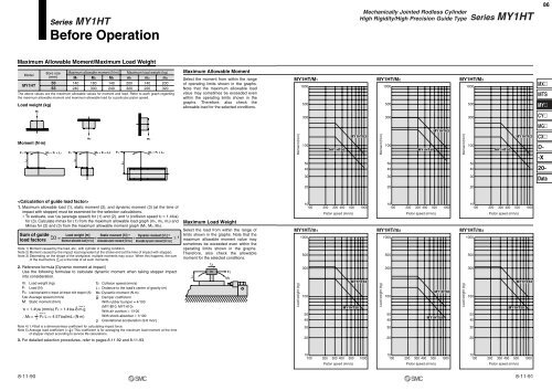
Series <strong>MY1</strong>HTBefore Operation<strong>Mechanically</strong> <strong>Jointed</strong> <strong>Rodless</strong> <strong>Cylinder</strong>High Rigidity/High Precision Guide TypeSeries <strong>MY1</strong>HT86Maximum Allowable Moment/Maximum Load WeightModel<strong>MY1</strong>HTLoad weight (kg)Bore size(mm)5063Maximum allowable moment (N·m)M1 M2 M3140240180300140240Maximum load weight (kg)m1 m2 m3200320140220200320The above values are the maximum allowable values for moment and load. Refer to each graph regardingthe maximum allowable moment and maximum allowable load for a particular piston speed.Maximum Allowable MomentSelect the moment from within the rangeof operating limits shown in the graphs.Note that the maximum allowable loadvalue may sometimes be exceeded evenwithin the operating limits shown in thegraphs. Therefore, also check theallowable load for the selected conditions.<strong>MY1</strong>HT/M11000500<strong>MY1</strong>HT/M21000500<strong>MY1</strong>HT/M31000500MXMTSMYm1300300300CYMoment (N·m)F1L1M1 = F1 x L1F2L2m2M2 = F2 x L2F3L3m3M3 = F3 x L3Moment (N·m)1005040<strong>MY1</strong>HT50<strong>MY1</strong>HT63Moment (N·m)1005040<strong>MY1</strong>HT50<strong>MY1</strong>HT63Moment (N·m)1005040<strong>MY1</strong>HT50<strong>MY1</strong>HT63MGCXD--X20-303030Data2020201. Maximum allowable load (1), static moment (2), and dynamic moment (3) (at the time ofimpact with stopper) must be examined for the selection calculations.∗ To evaluate, use υa (average speed) for (1) and (2), and υ (collision speed υ = 1.4υa)for (3). Calculate mmax for (1) from the maximum allowable load graph (m1, m2, m3) andMmax for (2) and (3) from the maximum allowable moment graph (M1, M2, M3).Sum of guideload factorsNote 1) Moment caused by the load, etc., with cylinder in resting condition.Note 2) Moment caused by the impact load equivalent at the stroke end (at the time of impact with stopper).Note 3) Depending on the shape of the workpiece, multiple moments may occur. When this happens, the sumof the load factors (∑α) is the total of all such moments.m: Load weight (kg)F: Load (N)FE: Load equivalent to impact (at impact with stopper) (N)υa: Average speed (mm/s)M: Static moment (N·m)Note 4)υ = 1.4υa (mm/s) FE = 1.4υa·δ·m·g∴ME =13Note 5)Σα = + + ≤ 1Load weight [m]Maximum allowable load [mmax]·FE·L1 = 4.57υaδmL1 (N·m)Static moment [M] (1)Allowable static moment [Mmax]υ: Collision speed (mm/s)L1: Distance to the load's center of gravity (m)ME: Dynamic moment (N·m)δ : Damper coefficientWith rubber bumper = 4/100(<strong>MY1</strong>B10, <strong>MY1</strong>H10)With air cushion = 1/100With shock absorber = 1/100g: Gravitational acceleration (9.8 m/s 2 )Dynamic moment [ME] (2)Allowable dynamic moment [MEmax]2. Reference formula [Dynamic moment at impact]Use the following formulae to calculate dynamic moment when taking stopper impactinto consideration.Maximum Load WeightSelect the load from within the range oflimits shown in the graphs. Note that themaximum allowable moment value maysometimes be exceeded even within theoperating limits shown in the graphs.Therefore, also check the allowablemoment for the selected conditions.L1υmFEME<strong>MY1</strong>HT/m1Load weight (kg)10100 200 300 400 500 1000Piston speed (mm/s)10005003001005040<strong>MY1</strong>HT63<strong>MY1</strong>HT501010100 200 300 400 500 1000 100 200 300 400 500 1000<strong>MY1</strong>HT/m2<strong>MY1</strong>HT/m3Load weight (kg)10005003001005040Piston speed (mm/s)<strong>MY1</strong>HT63<strong>MY1</strong>HT50Load weight (kg)10005003001005040Piston speed (mm/s)<strong>MY1</strong>HT63<strong>MY1</strong>HT50Note 4) 1.4υaδ is a dimensionless coefficient for calculating impact force.Note 5) Average load coefficient (= 1 ): This coefficient is for averaging the maximum load moment at the time3of stopper impact according to service life calculations.3. For detailed selection procedures, refer to pages 8-11-92 and 8-11-93.302030203020101010100 200 300 400 500 1000 100 200 300 400 500 1000 100 200 300 400 500 1000Piston speed (mm/s)Piston speed (mm/s)Piston speed (mm/s)8-11-908-11-91


