Synchrophasor Initiative in India - erldc
Synchrophasor Initiative in India - erldc
Synchrophasor Initiative in India - erldc

Create successful ePaper yourself
Turn your PDF publications into a flip-book with our unique Google optimized e-Paper software.
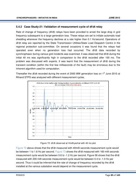
SYNCHROPHASORS - INITIATIVE IN INDIA JUNE 20125.4.2 Case Study-21: Validation of measurement cycle of df/dt relayRate of change of frequency (df/dt) relays have been provided to arrest the large drop <strong>in</strong> gridfrequency subsequent to a large generation loss. These relays are set to <strong>in</strong>itiate automatic loadshedd<strong>in</strong>g whenever the frequency decl<strong>in</strong>es at a rate higher than 0.1 Hz/second. Operations ofdf/dt relay are reported by the State Transmission Utilities/State Load Despatch Centre <strong>in</strong> theregional protection sub-committee. On several occasions it was found that the relays hadoperated even when no generation loss had occurred. The df/dt data recorded bysynchrophasor dur<strong>in</strong>g various grid <strong>in</strong>cidents was exam<strong>in</strong>ed. It was observed that df/dt dur<strong>in</strong>g the<strong>in</strong>itial 40 ms was significantly high <strong>in</strong> comparison to the df/dt recorded after 100 ms. Theproblem was discussed with experts. It was learnt that the measurement of df/dt dur<strong>in</strong>g thetransient condition (with<strong>in</strong> the first few milliseconds of the fault) may be erroneous due to the<strong>in</strong>herent algorithm used for computation.Thereafter the df/dt recorded dur<strong>in</strong>g the event of 2000 MW generation loss on 1 st June 2010 atRihand STPS was analyzed with different measurement cycles.Figure 72: df/dt observed at V<strong>in</strong>dhyachal with 40 ms plotFigure 72 above shows that the df/dt measured with 40milli seconds measurement cycle wouldbe between 1 to 1.6 Hz per second. Figure 73 shows the df/dt measured with 160 milli secondsmeasurement cycle would be between 0.6 to -1.2 Hz per second. Figure 58 shows that the df/dtmeasured with 200 milli seconds measurement cycle would be between 0.4 to -1.0 Hz persecond. Thus it could be <strong>in</strong>ferred that the rate of change of frequency recorded by the df/dt<strong>in</strong>stalled at the various substation would depend on the measurement cycle.POSOCO Page 83 of 143