Grundfos Alldos DDI-209 User Manual - Industry Surplus Australia
Grundfos Alldos DDI-209 User Manual - Industry Surplus Australia
Grundfos Alldos DDI-209 User Manual - Industry Surplus Australia

Create successful ePaper yourself
Turn your PDF publications into a flip-book with our unique Google optimized e-Paper software.
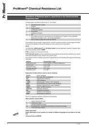
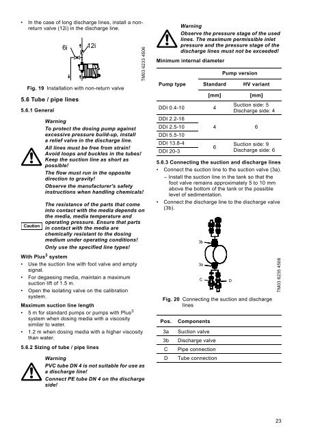
• In the case of long discharge lines, install a nonreturnvalve (12i) in the discharge line.Fig. 19 Installation with non-return valve5.6 Tube / pipe lines5.6.1 GeneralCaution6i12iWith Plus 3 system• Use the suction line with foot valve and emptysignal.• For degassing media, maintain a maximumsuction lift of 1.5 m.• Open the isolating valve on the calibrationsystem.Maximum suction line length• 5 m for standard pumps or pumps with Plus 3system when dosing media with a viscositysimilar to water.• 1.2 m when dosing media with a higher viscositythan water.5.6.2 Sizing of tube / pipe linesTM03 6233 4506WarningTo protect the dosing pump againstexcessive pressure build-up, installa relief valve in the discharge line.All lines must be free from strain!Avoid loops and buckles in the tubes!Keep the suction line as short aspossible!The flow must run in the oppositedirection to gravity!Observe the manufacturer's safetyinstructions when handling chemicals!The resistance of the parts that comeinto contact with the media depends onthe media, media temperature andoperating pressure. Ensure that partsin contact with the media arechemically resistant to the dosingmedium under operating conditions!Only use the specified line types!WarningPVC tube DN 4 is not suitable for use asa discharge line!Connect PE tube DN 4 on the dischargeside!WarningObserve the pressure stage of the usedlines. The maximum permissible inletpressure and the pressure stage of thedischarge lines must not be exceeded!Minimum internal diameterPump typeStandard[mm]<strong>DDI</strong> 0.4-10 4<strong>DDI</strong> 2.2-16<strong>DDI</strong> 2.5-10<strong>DDI</strong> 5.5-10<strong>DDI</strong> 13.8-4<strong>DDI</strong> 20-3Pump versionHV variant[mm]Suction side: 5Discharge side: 44 66Suction side: 9Discharge side: 65.6.3 Connecting the suction and discharge lines• Connect the suction line to the suction valve (3a).– Install the suction line in the tank so that thefoot valve remains approximately 5 to 10 mmabove the bottom of the tank or the possiblelevel of sedimentation.• Connect the discharge line to the discharge valve(3b).Fig. 20 Connecting the suction and dischargelinesPos.3a3bCD3b B3a ACCComponentsSuction valveDischarge valvePipe connectionTube connectionDDTM03 6235 450623