Grundfos Alldos DDI-209 User Manual - Industry Surplus Australia
Grundfos Alldos DDI-209 User Manual - Industry Surplus Australia
Grundfos Alldos DDI-209 User Manual - Industry Surplus Australia

Create successful ePaper yourself
Turn your PDF publications into a flip-book with our unique Google optimized e-Paper software.
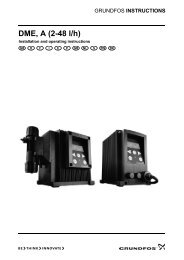
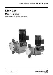
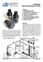
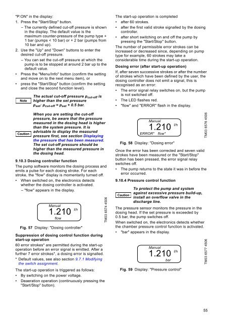
"P:ON" in the display:1. Press the "Start/Stop" button.– The currently defined cut-off pressure is shownin the display. The default value is themaximum counter-pressure of the pump type +1 bar (pumps < 10 bar) or + 2 bar (pumps from10 bar and up).2. Use the "Up" and "Down" buttons to enter thedesired cut-off pressure.– You can set the cut-off pressure at which thepump is to be stopped at around 2 bar up to thedefault value.• Press the "Menu/Info" button (confirm the settingand move on to the next menu item), or• press the "Start/Stop" button (confirm the settingand close the second function level).NoteCautionThe actual cut-off pressure p cut-off ishigher than the set pressurep set : p cut-off = p set + 0.5 bar.When you are setting the cut-offpressure, be aware that the pressuremeasured in the dosing head is higherthan the system pressure. It isadvisable to display the measuredpressure first, see section Displayingthe pressure that has been measured.The set cut-off pressure should behigher than the measured pressure inthe dosing head.9.10.3 Dosing controller functionThe pump software monitors the dosing process andemits a pulse for each dosing stroke. For eachstroke, the "flow" display is momentarily turned off.• When switched on, the electronics detectswhether the dosing controller is activated.– "flow" appears in the display.<strong>Manual</strong>1.210flowFig. 57 Display: "Dosing controller"Suppression of dosing control function duringstart-up operation60 error strokes* are permitted during the start-upoperation before an error signal is emitted. After afurther 7 error strokes*, a dosing error is signalled.* Default values, see also section 9.7.1 Modifyingthe switch assignment.The start-up operation is triggered as follows:• By switching on the power voltage.• Deaeration operation (continuously pressing the"Start/Stop" button).l/hTM03 6574 4506The start-up operation is completed• after 60 strokes.• after the first valid stroke signalled by the dosingcontroller.• after short switching on and off the pump bypressing the "Start/Stop" button.The number of permissible error strokes can beincreased or decreased since, depending on pumptype for example, 60 strokes may take aconsiderable time during the start-up operation.Dosing error (after start-up operation)If, after seven successive strokes or after the numberof strokes which have been defined by the user, thedosing controller does not emit a signal, this isrecognised as an error:• The error signal relay switches on, but the pumpis not switched off.• The LED flashes red.• "flow" and "ERROR" flash in the display.Fig. 58 Display: "Dosing error"Once the error has been corrected and seven validstrokes have been measured or the "Start/Stop"button has been pressed, the error signal relayswitches off.• The pump returns to the state it was in before theerror occurred.9.10.4 Pressure control functionCaution<strong>Manual</strong>1.210ERROR* flow*To protect the pump and systemagainst excessive pressure build-up,install an overflow valve in thedischarge line.The pressure sensor monitors the pressure in thedosing head. If the set pressure is exceeded by0.5 bar, the pump switches off.When switched on, the electronics detects whetherthe chamber pressure control function is activated.• "bar" appears in the display.<strong>Manual</strong>1.210barl/hl/hFig. 59 Display: "Pressure control"TM03 6576 4506TM03 6577 450655