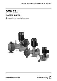
Grundfos Alldos DDI-209 User Manual - Industry Surplus Australia
Grundfos Alldos DDI-209 User Manual - Industry Surplus Australia
Grundfos Alldos DDI-209 User Manual - Industry Surplus Australia

You also want an ePaper? Increase the reach of your titles
YUMPU automatically turns print PDFs into web optimized ePapers that Google loves.
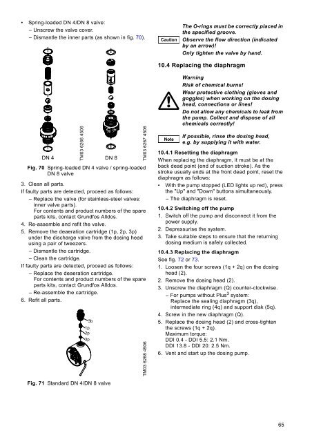
• Spring-loaded DN 4/DN 8 valve:– Unscrew the valve cover.– Dismantle the inner parts (as shown in fig. 70).CautionThe O-rings must be correctly placed inthe specified groove.Observe the flow direction (indicatedby an arrow)!Only tighten the valve by hand.10.4 Replacing the diaphragmTM03 6266 4506DN 4 DN 8Fig. 70 Spring-loaded DN 4 valve / spring-loadedDN 8 valve3. Clean all parts.If faulty parts are detected, proceed as follows:– Replace the valve (for stainless-steel valves:inner valve parts).For contents and product numbers of the spareparts kits, contact <strong>Grundfos</strong> <strong>Alldos</strong>.4. Re-assemble and refit the valve.5. Remove the deaeration cartridge (1p, 2p, 3p)under the discharge valve from the dosing headusing a pair of tweezers.– Dismantle the cartridge.– Clean the cartridge.If faulty parts are detected, proceed as follows:– Replace the deaeration cartridge.For contents and product numbers of the spareparts kits, contact <strong>Grundfos</strong> <strong>Alldos</strong>.– Re-assemble the cartridge.6. Refit all parts.3b1p2p3pTM03 6267 4506TM03 6268 4506NoteWarningRisk of chemical burns!Wear protective clothing (gloves andgoggles) when working on the dosinghead, connections or lines!Do not allow any chemicals to leak fromthe pump. Collect and dispose of allchemicals correctly!If possible, rinse the dosing head,e.g. by supplying it with water.10.4.1 Resetting the diaphragmWhen replacing the diaphragm, it must be at theback dead point (end of suction stroke). As thestroke usually ends at the front dead point, reset thediaphragm as follows:• With the pump stopped (LED lights up red), pressthe "Up" and "Down" buttons simultaneously.– The diaphragm is reset.10.4.2 Switching off the pump1. Switch off the pump and disconnect it from thepower supply.2. Depressurise the system.3. Take suitable steps to ensure that the returningdosing medium is safely collected.10.4.3 Replacing the diaphragmSee fig. 72 or 73.1. Loosen the four screws (1q + 2q) on the dosinghead (2).2. Remove the dosing head (2).3. Unscrew the diaphragm (Q) counter-clockwise.– For pumps without Plus 3 system:Replace the sealing diaphragm (3q),intermediate ring (4q) and support disk (5q).4. Screw in the new diaphragm (Q).5. Replace the dosing head (2) and cross-tightenthe screws (1q + 2q).Maximum torque:<strong>DDI</strong> 0.4 - <strong>DDI</strong> 5.5: 2.1 Nm.<strong>DDI</strong> 13.8 - <strong>DDI</strong> 20: 2.5 Nm.6. Vent and start up the dosing pump.Fig. 71 Standard DN 4/DN 8 valve65