- Page 1 and 2:
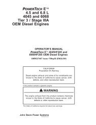
PowerTech4.5 L and 6.8 LNon-Certifi
- Page 3 and 4:
Introduction• PE4045TF151• PE40
- Page 5 and 6:
IntroductionPOWERTECH ® 4.5 L Engi
- Page 7 and 8:
ContentsPagePageRecord Keeping Inst
- Page 9 and 10:
Record KeepingPOWERTECH ® Medallio
- Page 11 and 12:
Record KeepingEngine Option CodesEn
- Page 13 and 14:
Record KeepingRecord Fuel Injection
- Page 15 and 16:
SafetyReplace Safety SignsReplace m
- Page 17 and 18:
SafetyService Machines SafelyTie lo
- Page 19 and 20:
SafetyPractice Safe MaintenanceUnde
- Page 21 and 22:
SafetyRemove Paint Before Welding o
- Page 23 and 24:
SafetyAvoid Harmful Asbestos DustAv
- Page 25 and 26:
SafetyProtect Against High Pressure
- Page 27 and 28:
Fuels, Lubricants, and CoolantDiese
- Page 29 and 30:
Fuels, Lubricants, and CoolantBio-D
- Page 31 and 32:
Fuels, Lubricants, and CoolantMinim
- Page 33 and 34:
Fuels, Lubricants, and CoolantDiese
- Page 35 and 36:
Fuels, Lubricants, and CoolantOILSC
- Page 37 and 38:
Fuels, Lubricants, and CoolantGreas
- Page 39 and 40:
Fuels, Lubricants, and CoolantWater
- Page 41 and 42:
Fuels, Lubricants, and CoolantEthyl
- Page 43 and 44:
Fuels, Lubricants, and CoolantEthyl
- Page 45 and 46:
Engine Operating GuidelinesInstrume
- Page 47 and 48:
Engine Operating GuidelinesThe rese
- Page 49 and 50:
Engine Operating GuidelinesG—Batt
- Page 51 and 52: Engine Operating GuidelinesIMPORTAN
- Page 53 and 54: Engine Operating GuidelinesAuxiliar
- Page 55 and 56: Engine Operating GuidelinesNOTE: El
- Page 57 and 58: Engine Operating GuidelinesNormal E
- Page 59 and 60: Engine Operating GuidelinesChanging
- Page 61 and 62: Engine Operating GuidelinesUsing a
- Page 63 and 64: Lubrication and MaintenanceObserve
- Page 65 and 66: Lubrication and MaintenanceCheck Ai
- Page 67 and 68: Lubrication and MaintenanceReplace
- Page 69 and 70: Lubrication & Maintenance/DailyCAUT
- Page 71 and 72: Lubrication & Maintenance/Daily4. I
- Page 73 and 74: Lubrication & Maintenance/250 Hour/
- Page 75 and 76: Lubrication & Maintenance/250 Hour/
- Page 77 and 78: Lubrication & Maintenance/250 Hour/
- Page 79 and 80: Lubrication & Maintenance/250 Hour/
- Page 81 and 82: Lubrication & Maintenance/500 Hour/
- Page 83 and 84: Lubrication & Maintenance/500 Hour/
- Page 85 and 86: Lubrication & Maintenance/500 Hour/
- Page 87 and 88: Lubrication & Maintenance/500 Hour/
- Page 89 and 90: Lubrication & Maintenance/500 Hour/
- Page 91 and 92: Lubrication & Maintenance/500 Hour/
- Page 93 and 94: Lubrication & Maintenance/500 Hour/
- Page 95 and 96: Lubrication & Maint./2000 Hour/24 M
- Page 97 and 98: Lubrication & Maint./2000 Hour/24 M
- Page 99 and 100: Lubrication & Maint./2000 Hour/24 M
- Page 101: Lubrication & Maint./2000 Hour/24 M
- Page 105 and 106: Lubrication & Maint./2000 Hour/24 M
- Page 107 and 108: Service as RequiredAdding CoolantCA
- Page 109 and 110: Service as RequiredReplacing Axial
- Page 111 and 112: Service as RequiredReplacing Radial
- Page 113 and 114: Service as RequiredReplacing Fan an
- Page 115 and 116: Service as RequiredChecking Air Com
- Page 117 and 118: Service as RequiredIMPORTANT: Do no
- Page 119 and 120: Service as RequiredOn DENSO and Mot
- Page 121 and 122: Troubleshooting50-2 110306PN=121
- Page 123 and 124: TroubleshootingWiring Diagram (Stan
- Page 125 and 126: TroubleshootingEngine Wiring Diagra
- Page 127 and 128: TroubleshootingSymptom Problem Solu
- Page 129 and 130: TroubleshootingSymptom Problem Solu
- Page 131 and 132: TroubleshootingSymptom Problem Solu
- Page 133 and 134: StorageEngine Storage Guidelines1.
- Page 135 and 136: Storage15. Store the engine in a dr
- Page 137 and 138: SpecificationsGeneral OEM Engine Sp
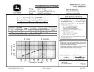
- Page 139 and 140: SpecificationsPOWER RATINGS ON DYNA
- Page 141 and 142: SpecificationsPOWER RATINGS ON DYNA
- Page 143 and 144: SpecificationsPOWER RATINGS ON DYNA
- Page 145 and 146: SpecificationsPOWER RATINGS ON DYNA
- Page 147 and 148: SpecificationsEngine Model Oil Pan
- Page 149 and 150: SpecificationsEngine Crankcase Oil
- Page 151 and 152: SpecificationsMetric Bolt and Screw
- Page 153 and 154:
Lubrication and Maintenance Records
- Page 155 and 156:
Lubrication and Maintenance Records
- Page 157 and 158:
Emission System WarrantyU.S. EPA Em
- Page 159 and 160:
John Deere Service Literature Avail
- Page 161 and 162:
IndexPagePageA Check ..............
- Page 163 and 164:
IndexPagePageEngine serial number .