- Page 4 and 5:
338 Installation and Mainframe Conf
- Page 6 and 7:
340 Installation and Mainframe Conf
- Page 8:
342 lnstallation and Mainframe Conf
- Page 12 and 13:
346 Installation and Mainframe Conf
- Page 14 and 15:
348 Installation and Mainframe Conf
- Page 16 and 17:
350 Installation and Mainframe Conf
- Page 18 and 19:
352 Installation and Mainframe Conf
- Page 20 and 21:
354 Installation and Mainframe Conf
- Page 22 and 23:
356 Installation 2nd Mainframe Conf
- Page 24 and 25:
358 Insidlation and Mainframe Confi
- Page 26 and 27:
360 Installation and Mainframe Conf
- Page 28 and 29:
362 Installation and Mainframe Conf
- Page 30 and 31:
364 Installation and Mainframe Conf
- Page 32 and 33:
366 Installation and Mainframe Conf
- Page 34 and 35:
368 :nstzllstion 2nd Mainframe Conf
- Page 36 and 37:
370 Plug-In Assembly ConfigurationI
- Page 38 and 39: 372 Plug-in Assembly ConfigurationF
- Page 40 and 41: 374 Plug-In Assembly ConfigurationI
- Page 42 and 43: 376 Plug-in Assembly ConfigurationR
- Page 44 and 45: 378 Plug-In Assembly Configuration-
- Page 46 and 47: 380 Plug-In Assembly ConfigurationT
- Page 48 and 49: 382 Plug-In Assembly Configuration1
- Page 50 and 51: 384 Plug-In Assembly ConfigurationI
- Page 52 and 53: 386 Plug-In Assembly ConfigurationT
- Page 54 and 55: 388 Plug-In Assembly ConfigurationF
- Page 56 and 57: 390 Plug-In Assembly ConfigurationT
- Page 58 and 59: 392 Plug-In Assembly ConfigurationS
- Page 60 and 61: 394 Plug-In Assembly ConfigurationJ
- Page 62 and 63: 396 Plug-In Assembly Configurationl
- Page 64 and 65: 398 Plug-In Assembly ConfigurationC
- Page 66 and 67: 400 Plug-In Assembly ConfigurationF
- Page 68 and 69: 402 Plug-In Assembly ConfigurationD
- Page 70 and 71: 404 Plug-In Assembly ConfigurationM
- Page 72 and 73: 406 Plug-In Assembly ConfigurationC
- Page 74 and 75: 408 Plug-In Assembly ConfigurationL
- Page 76 and 77: 41 0 Plug-In Assembly Configuration
- Page 78 and 79: 41 2 Plug-In Assembly Configuration
- Page 80 and 81: 41 4 Plug-in Assembly Configuration
- Page 82 and 83: 41 6 Plug-In Assembly Configufation
- Page 84 and 85: 41 8 Plug-In Assembly Configuration
- Page 86 and 87: 420 Plug-In Assembly ConfigurationN
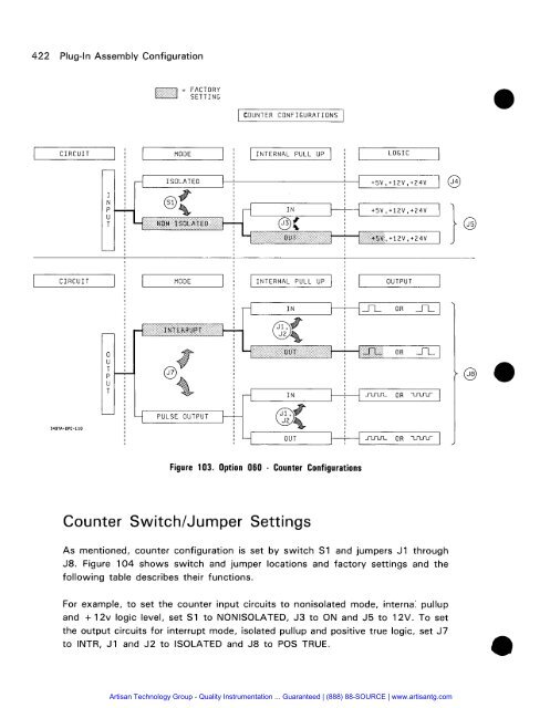
- Page 90 and 91: 424 Plug-In Assembly ConfigurationS
- Page 92 and 93: 426 Plug-In Assembly ConfigurationI
- Page 94 and 95: 428 Plug-In Assembly ConfigurationS
- Page 96 and 97: 430 Plug-In Assembly ConfigurationW
- Page 98 and 99: 432 Plug-in Assembly ConfigurationC
- Page 100 and 101: 434 Plug-In Assembly ConfigurationT
- Page 102 and 103: 436 Plug-In Assembly ConfigurationS
- Page 104 and 105: 438 Plug-in Assembly ConfigurationM
- Page 106 and 107: 440 Plug-In Assembly ConfigurationA
- Page 108 and 109: 442 Plug-in Assembly ConfigurationI
- Page 110 and 111: -444 Plug-In Assembly Configuration
- Page 112 and 113: 446 Plug-in Assembly Configuration1
- Page 114 and 115: -448 Plug-In Assembly Configuration
- Page 116 and 117: 450 Plug-In Assembly ConfigurationM
- Page 118: 452 Plug-In Assembly ConfigurationF
- Page 121 and 122: Plug-In Assembly Configuration &5WI
- Page 123 and 124: Plug-In Assembly Configuration 4571
- Page 125 and 126: Plug-In Assembly Configuration 459N
- Page 127 and 128: Plug-In Assembly Configuration 461R
- Page 129 and 130: Plug-In Assembly Configuration 463I
- Page 131 and 132: CQ\1!~~G~L3~\~~'L': irL: ASsELv3rL,
- Page 133 and 134: Plug-In Assembly Configuration 467O
- Page 135 and 136: Plug-In Assembly Configuration 469T
- Page 137 and 138: Plug-In Assembly Configuration 47 1
- Page 139 and 140:
Plug-in Assembly Configuration 4.73
- Page 141 and 142:
Plug-In Assembly Configuration 475M
- Page 143 and 144:
Plug-In Assembly Configuration 477S
- Page 145 and 146:
Plug-In Assembly Configuration 4791
- Page 147 and 148:
Plug-In Assembly Configuration 48'1
- Page 149 and 150:
Plug-In Assembly Configuration 4833
- Page 151 and 152:
Plug-In Assembly Configuration 485T
- Page 153 and 154:
Plug-In Assembly Configuration 487D
- Page 155 and 156:
Plug-In Assembly Configuration 489D
- Page 157 and 158:
Plug-In Assembly Configuration 49 4
- Page 159 and 160:
Plug-In Assembly Configuration 493(
- Page 161 and 162:
Plug-In Assembly Configuration 495I
- Page 163 and 164:
Plug-In Assembly Configuration 497B
- Page 165 and 166:
Plug-in Assembly Configuration 499C
- Page 167 and 168:
502 Plug-In Assembly ConfigurationC
- Page 169 and 170:
504 Plug-In Assembly ConfigurationM
- Page 171 and 172:
506 Plug-In Assembly ConfigurationI
- Page 173 and 174:
508 Plug-In Assembly ConfigurationR
- Page 175 and 176:
51 0 Plug-In Assembly Configuration
- Page 177 and 178:
51 2 Plug-In Assembly Configuration
- Page 179 and 180:
51 4 Plug-In Assembly Configuration
- Page 181 and 182:
5 9 6 Plug-In Assembly Configuratio
- Page 183 and 184:
51 8 Plug-In Assembly Configuration
- Page 185 and 186:
520 Plug-In Assembly ConfigurationV
- Page 187 and 188:
Artisan Technology Group - Quality
- Page 189 and 190:
524 Plug-In Assembly ConfigurationT
- Page 191 and 192:
526 Plug-In Assembly ConfigurationI
- Page 193 and 194:
528 Plug-In Assembly ConfigurationU
- Page 195 and 196:
530 Plug-In Assembly ConfigurationU
- Page 197 and 198:
532 Plug-In Assembly ConfigurationC
- Page 199 and 200:
Plug-In Assembly Configuration 533T
- Page 201 and 202:
Plug-In Assembly Configuration 535N
- Page 203 and 204:
Plug-In Assembly Configuration 537\
- Page 205 and 206:
Plug-In Assembly Configuration 5391
- Page 207 and 208:
Interfacing the 3498A with the 3497
- Page 209 and 210:
Plug-In Assembly Configuration 543(
- Page 211 and 212:
I SUGGESTED SLOT # AND CHANNEL ADDR
- Page 213 and 214:
Plug-In Assembly Configuration 547C
- Page 215 and 216:
Plug-In Assembly Configuration 549D
- Page 217 and 218:
Plug-In Assembly Configuration 551O
- Page 219 and 220:
554 Example 3497A ConfigurationsI E
- Page 221 and 222:
556 Example 3497A Configurations1 T
- Page 223 and 224:
558 Example 3497A ConfigurationsEXA
- Page 225 and 226:
560 Example 3497A ConfigurationsSAM
- Page 227 and 228:
562 Example 3497A ConfigurationsSIN
- Page 229 and 230:
564 Example 3497A ConfigurationsCON
- Page 231 and 232:
566 Example 3497A ConfigurationsSLO
- Page 233 and 234:
568 Example 3497A ConfigurationsEXA
- Page 235 and 236:
570 Example 3497A ConfigurationsSAM
- Page 237 and 238:
572 Example 3497A Configurations( A
- Page 239 and 240:
574 Example 3497A ConfigurationsVM
- Page 241 and 242:
576 Example 3497A ConfigurationsEXA
- Page 243 and 244:
578 Example 3497A ConfigurationsSAM
- Page 245 and 246:
580 Example 3497A ConfigurationsDEC
- Page 247 and 248:
582 Example 3497A ConfigurationsEXA
- Page 249 and 250:
584 Example 3497A ConfigurationsSET
- Page 251 and 252:
586 Example 3497A ConfigurationsEXA
- Page 253 and 254:
588 Example 3497A ConfigurationsINS
- Page 255 and 256:
592 Example 3497A ConfigurationsEXA
- Page 257 and 258:
594 Example 3497A ConfigurationsI C
- Page 259 and 260:
596 Example 3497A ConfigurationsPER
- Page 261 and 262:
598 Example 3497A ConfigurationsEXA
- Page 263 and 264:
600 Example 3497A ConfigurationsSAM
- Page 265 and 266:
602 Example 3497A ConfigurationsEXA
- Page 267 and 268:
604 Example 3497A ConfigurationsINT
- Page 269 and 270:
606 Example 3497A ConfigurationsI P
- Page 271 and 272:
608 Example 3497A ConfigurationsEXA
- Page 273 and 274:
61 0 Example 3497A ConfigurationsSA
- Page 275 and 276:
61 2 Example 3497A ConfigurationsTO
- Page 277 and 278:
61 4 Example 3497A ConfigurationsEX
- Page 279 and 280:
6 1 6 Example 3497A ConfigurationsE
- Page 281 and 282:
61 8 Example 3497A ConfigurationsSE
- Page 283 and 284:
620 Example 3497A ConfigurationsEXA
- Page 285 and 286:
622 Example 3497A Configurations0VO
- Page 287 and 288:
624 Interface ConceptsHP-IBBUS COMP
- Page 289 and 290:
626 Interface Concepts( HP-IB DEVIC
- Page 291 and 292:
628 Interface ConceptsASCll TableFo
- Page 293 and 294:
630 Interface ConceptsSYNCHRONOUSAS
- Page 295 and 296:
632 Interface ConceptsStart BitThe
- Page 297 and 298:
634 Interface ConceptsAn asynchrono
- Page 299 and 300:
636 Interface Concepts'Figure A-7 2
- Page 301 and 302:
638 Interface Concepts0 The time re
- Page 303 and 304:
640 Interface ConceptsData Circuits
- Page 305 and 306:
642 Interface ConceptsCircuit CG (C
- Page 307 and 308:
644 Interface ConceptsRS449 Pin Ide
- Page 309 and 310:
646 Specifications and General Info
- Page 311 and 312:
648 Specifications and General Info
- Page 313 and 314:
650 Specifications and General Info
- Page 315 and 316:
652 Specifications and General Info
- Page 317 and 318:
654 Specifications and General lnfo
- Page 319 and 320:
656 Specifications and General Info
- Page 321 and 322:
658 Specifications and General Info
- Page 323 and 324:
660 Specifications and General Info
- Page 325 and 326:
662 Specifications and General Info
- Page 327 and 328:
664 Specifications and General Info
- Page 329 and 330:
Artisan Technology Group - Quality
- Page 331 and 332:
'SALES & SUPPORT OFFICESArranged al
- Page 333 and 334:
1 11 11 INECESSARYBUSINESS REPLY CA
- Page 335 and 336:
TABLE OF CONTENTS (Cont'd)ChapterPa
- Page 337 and 338:
INDEXAPageAlarm (BEEP).............
- Page 339 and 340:
GPageGETTING STARTED Flowchart ....
- Page 341 and 342:
Resistance Measurements. 4-Wire (Ex
- Page 343:
Artisan Technology Group is your so