

PDF version - ARM Information Center
PDF version - ARM Information Center
PDF version - ARM Information Center

Create successful ePaper yourself
Turn your PDF publications into a flip-book with our unique Google optimized e-Paper software.
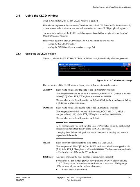
Getting Started with Real-Time System Models2.5 Using the CLCD windowWhen a RTSM starts, the RTSM CLCD window is opened.This window represents the contents of the simulated color LCD frame buffer. It automaticallyresizes to match the horizontal and vertical resolution set in the CLCD peripheral registers.For more information on the CLCD model components and other peripherals, see the FastModels Reference Manual.This section describes the CLCD window for VE RTSMs and MPS RTSMs:• Using the VE CLCD window• Using the MPS Visualization window on page 2-92.5.1 Using the VE CLCD windowFigure 2-1 shows the VE RTSM CLCD in its default state, immediately after being started.Figure 2-1 CLCD window at startupThe top section of the CLCD window displays the following status information:USERSWBOOTSWEight white boxes show the state of the VE User DIP switches:These represent switch S6 on the VE hardware, USERSW[8:1], which is mappedto bits [7:0] of the SYS_SW register at address 0x10000004.The switches are in the off position by default. Click in the area above or belowa white box to change its state.Eight white boxes showing the state of the VE Boot DIP switches.These represent switch S8 on the VE hardware, BOOTSEL[8:1], which ismapped to bits [15:8] of the SYS_SW register at address 0x100000004.The switches are in the off position by default.Note<strong>ARM</strong> recommends you configure the Boot DIP switches using the boot_switchmodel parameter rather than by using the CLCD interface.Changing Boot DIP switch positions while the model is running can result inunpredictable behavior.S6LEDTotal InstrEight colored boxes indicate the state of the VE User LEDs.These represent LEDs D[21:14] on the VE hardware, which are mapped to bits[7:0] of the SYS_LED register at address 0x10000008. The boxes correspond to thered/yellow/green LEDs on the VE hardware.A counter showing the total number of instructions executed.Because the RTSM models provide a programmer’s view of the system, theCLCD displays total instructions rather than total core cycles. Timing mightdiffer substantially from the hardware because:• the bus fabric is simplified<strong>ARM</strong> DUI 0575A Copyright © 2011 <strong>ARM</strong>. All rights reserved. 2-7ID051811Non-Confidential


