MPhil thesis of Lo Chi Wa - Department of Electronic & Computer ...
MPhil thesis of Lo Chi Wa - Department of Electronic & Computer ...
MPhil thesis of Lo Chi Wa - Department of Electronic & Computer ...
Create successful ePaper yourself
Turn your PDF publications into a flip-book with our unique Google optimized e-Paper software.
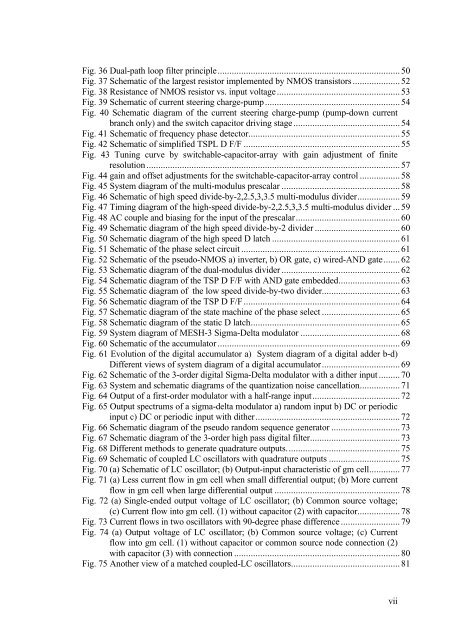
Fig. 36 Dual-path loop filter principle.............................................................................50Fig. 37 Schematic <strong>of</strong> the largest resistor implemented by NMOS transistors ....................52Fig. 38 Resistance <strong>of</strong> NMOS resistor vs. input voltage....................................................53Fig. 39 Schematic <strong>of</strong> current steering charge-pump.........................................................54Fig. 40 Schematic diagram <strong>of</strong> the current steering charge-pump (pump-down currentbranch only) and the switch capacitor driving stage.............................................54Fig. 41 Schematic <strong>of</strong> frequency phase detector................................................................55Fig. 42 Schematic <strong>of</strong> simplified TSPL D F/F ..................................................................55Fig. 43 Tuning curve by switchable-capacitor-array with gain adjustment <strong>of</strong> finiteresolution ...........................................................................................................57Fig. 44 gain and <strong>of</strong>fset adjustments for the switchable-capacitor-array control .................58Fig. 45 System diagram <strong>of</strong> the multi-modulus prescalar ..................................................58Fig. 46 Schematic <strong>of</strong> high speed divide-by-2,2.5,3,3.5 multi-modulus divider..................59Fig. 47 Timing diagram <strong>of</strong> the high-speed divide-by-2,2.5,3,3.5 multi-modulus divider ...59Fig. 48 AC couple and biasing for the input <strong>of</strong> the prescalar............................................60Fig. 49 Schematic diagram <strong>of</strong> the high speed divide-by-2 divider ....................................60Fig. 50 Schematic diagram <strong>of</strong> the high speed D latch ......................................................61Fig. 51 Schematic <strong>of</strong> the phase select circuit ...................................................................61Fig. 52 Schematic <strong>of</strong> the pseudo-NMOS a) inverter, b) OR gate, c) wired-AND gate.......62Fig. 53 Schematic diagram <strong>of</strong> the dual-modulus divider ..................................................62Fig. 54 Schematic diagram <strong>of</strong> the TSP D F/F with AND gate embedded..........................63Fig. 55 Schematic diagram <strong>of</strong> the low speed divide-by-two divider.................................63Fig. 56 Schematic diagram <strong>of</strong> the TSP D F/F ..................................................................64Fig. 57 Schematic diagram <strong>of</strong> the state machine <strong>of</strong> the phase select .................................65Fig. 58 Schematic diagram <strong>of</strong> the static D latch...............................................................65Fig. 59 System diagram <strong>of</strong> MESH-3 Sigma-Delta modulator ..........................................68Fig. 60 Schematic <strong>of</strong> the accumulator .............................................................................69Fig. 61 Evolution <strong>of</strong> the digital accumulator a) System diagram <strong>of</strong> a digital adder b-d)Different views <strong>of</strong> system diagram <strong>of</strong> a digital accumulator.................................69Fig. 62 Schematic <strong>of</strong> the 3-order digital Sigma-Delta modulator with a dither input .........70Fig. 63 System and schematic diagrams <strong>of</strong> the quantization noise cancellation.................71Fig. 64 Output <strong>of</strong> a first-order modulator with a half-range input.....................................72Fig. 65 Output spectrums <strong>of</strong> a sigma-delta modulator a) random input b) DC or periodicinput c) DC or periodic input with dither.............................................................72Fig. 66 Schematic diagram <strong>of</strong> the pseudo random sequence generator .............................73Fig. 67 Schematic diagram <strong>of</strong> the 3-order high pass digital filter......................................73Fig. 68 Different methods to generate quadrature outputs................................................75Fig. 69 Schematic <strong>of</strong> coupled LC oscillators with quadrature outputs ..............................75Fig. 70 (a) Schematic <strong>of</strong> LC oscillator; (b) Output-input characteristic <strong>of</strong> gm cell.............77Fig. 71 (a) Less current flow in gm cell when small differential output; (b) More currentflow in gm cell when large differential output .....................................................78Fig. 72 (a) Single-ended output voltage <strong>of</strong> LC oscillator; (b) Common source voltage;(c) Current flow into gm cell. (1) without capacitor (2) with capacitor..................78Fig. 73 Current flows in two oscillators with 90-degree phase difference .........................79Fig. 74 (a) Output voltage <strong>of</strong> LC oscillator; (b) Common source voltage; (c) Currentflow into gm cell. (1) without capacitor or common source node connection (2)with capacitor (3) with connection ......................................................................80Fig. 75 Another view <strong>of</strong> a matched coupled-LC oscillators..............................................81vii


