MPhil thesis of Lo Chi Wa - Department of Electronic & Computer ...
MPhil thesis of Lo Chi Wa - Department of Electronic & Computer ...
MPhil thesis of Lo Chi Wa - Department of Electronic & Computer ...
Create successful ePaper yourself
Turn your PDF publications into a flip-book with our unique Google optimized e-Paper software.
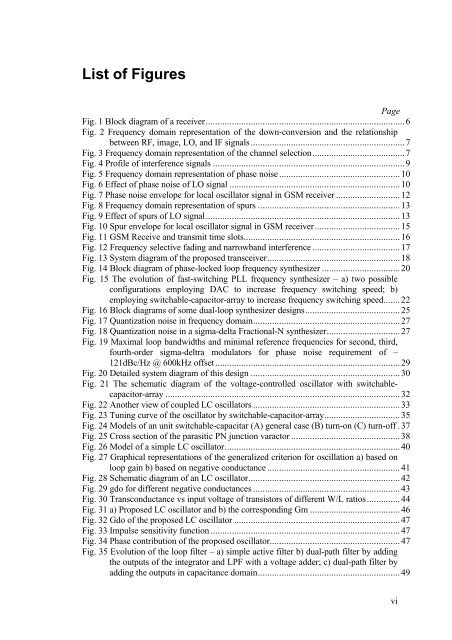
List <strong>of</strong> FiguresPageFig. 1 Block diagram <strong>of</strong> a receiver....................................................................................6Fig. 2 Frequency domain representation <strong>of</strong> the down-conversion and the relationshipbetween RF, image, LO, and IF signals .................................................................7Fig. 3 Frequency domain representation <strong>of</strong> the channel selection.......................................7Fig. 4 Pr<strong>of</strong>ile <strong>of</strong> interference signals .................................................................................9Fig. 5 Frequency domain representation <strong>of</strong> phase noise ...................................................10Fig. 6 Effect <strong>of</strong> phase noise <strong>of</strong> LO signal ........................................................................10Fig. 7 Phase noise envelope for local oscillator signal in GSM receiver ...........................12Fig. 8 Frequency domain representation <strong>of</strong> spurs ............................................................13Fig. 9 Effect <strong>of</strong> spurs <strong>of</strong> LO signal..................................................................................13Fig. 10 Spur envelope for local oscillator signal in GSM receiver....................................15Fig. 11 GSM Receive and transmit time slots..................................................................16Fig. 12 Frequency selective fading and narrowband interference .....................................17Fig. 13 System diagram <strong>of</strong> the proposed transceiver........................................................18Fig. 14 Block diagram <strong>of</strong> phase-locked loop frequency synthesizer .................................20Fig. 15 The evolution <strong>of</strong> fast-switching PLL frequency synthesizer – a) two possibleconfigurations employing DAC to increase frequency switching speed; b)employing switchable-capacitor-array to increase frequency switching speed.......22Fig. 16 Block diagrams <strong>of</strong> some dual-loop synthesizer designs........................................25Fig. 17 Quantization noise in frequency domain..............................................................27Fig. 18 Quantization noise in a sigma-delta Fractional-N synthesizer...............................27Fig. 19 Maximal loop bandwidths and minimal reference frequencies for second, third,fourth-order sigma-deltra modulators for phase noise requirement <strong>of</strong> –121dBc/Hz @ 600kHz <strong>of</strong>fset..............................................................................29Fig. 20 Detailed system diagram <strong>of</strong> this design ...............................................................30Fig. 21 The schematic diagram <strong>of</strong> the voltage-controlled oscillator with switchablecapacitor-array...................................................................................................32Fig. 22 Another view <strong>of</strong> coupled LC oscillators ..............................................................33Fig. 23 Tuning curve <strong>of</strong> the oscillator by switchable-capacitor-array................................35Fig. 24 Models <strong>of</strong> an unit switchable-capacitar (A) general case (B) turn-on (C) turn-<strong>of</strong>f .37Fig. 25 Cross section <strong>of</strong> the parasitic PN junction varactor ..............................................38Fig. 26 Model <strong>of</strong> a simple LC oscillator..........................................................................40Fig. 27 Graphical representations <strong>of</strong> the generalized criterion for oscillation a) based onloop gain b) based on negative conductance ........................................................41Fig. 28 Schematic diagram <strong>of</strong> an LC oscillator................................................................42Fig. 29 gdo for different negative conductances ..............................................................43Fig. 30 Transconductance vs input voltage <strong>of</strong> transistors <strong>of</strong> different W/L ratios..............44Fig. 31 a) Proposed LC oscillator and b) the corresponding Gm ......................................46Fig. 32 Gdo <strong>of</strong> the proposed LC oscillator ......................................................................47Fig. 33 Impulse sensitivity function ................................................................................47Fig. 34 Phase contribution <strong>of</strong> the proposed oscillator.......................................................47Fig. 35 Evolution <strong>of</strong> the loop filter – a) simple active filter b) dual-path filter by addingthe outputs <strong>of</strong> the integrator and LPF with a voltage adder; c) dual-path filter byadding the outputs in capacitance domain............................................................49vi


