Data Acquisition and Processing Report (DAPR) - Center for Coastal ...
Data Acquisition and Processing Report (DAPR) - Center for Coastal ...
Data Acquisition and Processing Report (DAPR) - Center for Coastal ...

Create successful ePaper yourself
Turn your PDF publications into a flip-book with our unique Google optimized e-Paper software.
(latency) between the time positioning data is received, <strong>and</strong> the time the computed<br />
position reaches the acquisition system. To ensure quality results from the patch test<br />
procedure it is necessary to have a relatively calm sea state, collection of clean data <strong>and</strong> a<br />
helmsman that can stay online during the procedure. Static transducer draft, settlement<br />
<strong>and</strong> squat corrections, sound velocity corrections, <strong>and</strong> preliminary tide corrections will be<br />
applied to the data prior to bias determination. The general patch test procedure requires<br />
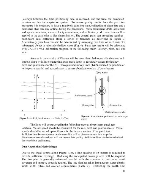
multibeam data collection along a series of transects as described in Figure 3.<br />
Alternatively, yaw bias can also be determined by surveying two lines on each side of a<br />
submerged object in relatively shallow water (Fig. 4). Patch test results will be calculated<br />
with CARIS’s v6.1 calibration program in the following order: Latency, pitch, roll <strong>and</strong><br />
yaw.<br />
An area in the vicinity of Vieques will be been identified to provide the steep <strong>and</strong><br />
smooth slope with little change in across track depth to accurately assess the latency,<br />
pitch <strong>and</strong> yaw biases <strong>for</strong> the NF. Two planned survey lines (1&2) oriented perpendicular<br />
to slope are parallel <strong>and</strong> spaced apart to ensure abundant overlap of outer beams.<br />
Figure 3: a = Roll, b = Latency, c = Pitch, d =Yaw<br />
Figure 4: Yaw bias test per<strong>for</strong>med on submerged<br />
object<br />
The lines will be surveyed in the following order at the primary patch test<br />
location. Vessel speed should be consistent <strong>for</strong> the roll, pitch <strong>and</strong> yaw transects. Vessel<br />
speeds should be varied up to 5 knots <strong>for</strong> the latency section of the patch test.<br />
Sufficient time between passes on the same line will be given to ensure ship propeller<br />
disturbances have cleared <strong>and</strong> will not impact data quality. Additional lines can be included <strong>and</strong><br />
the schedule is preliminary.<br />
<strong>Data</strong> <strong>Acquisition</strong> Methodology:<br />
Due to the shoal depths along Puerto Rico, a line spacing of 55 meters is required to<br />
provide sufficient coverage. Reducing the anticipated coverage area will be required.<br />
The line plan is generally orientated parallel with the contours to maximize swath<br />
coverage <strong>and</strong> improve acoustic returns. The line plan has taken into account water depths,<br />
swath width filters <strong>and</strong> overlap requirements (Table 2). Restricting the swath limit<br />
118