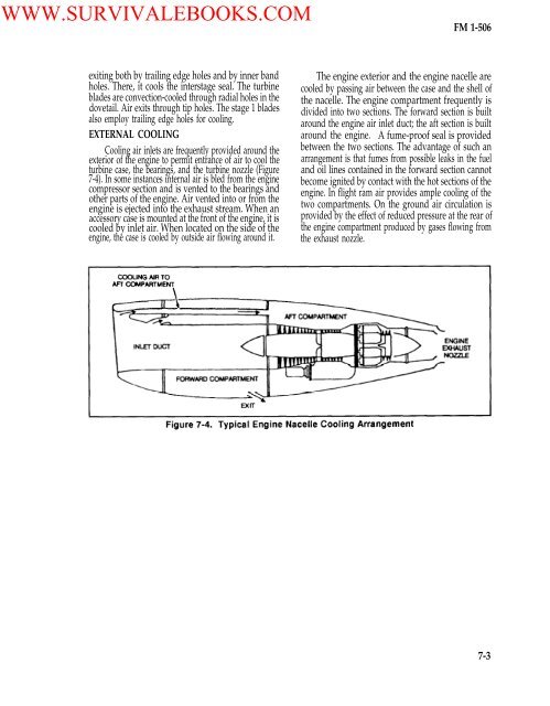
WWW.SURVIVALEBOOKS.COM<strong>FM</strong> 1-<strong>506</strong>exiting both by trailing edge holes and by inner bandholes. There, it cools the interstage seal. The turbineblades are convection-cooled through radial holes in thedovetail. Air exits through tip holes. The stage 1 bladesalso employ trailing edge holes for cooling.EXTERNAL COOLINGCooling air inlets are frequently provided around theexterior <strong>of</strong> the engine to permit entrance <strong>of</strong> air to cool theturbine case, the bearings, and the turbine nozzle (Figure7-4). In some instances internal air is bled from the enginecompressor section and is vented to the bearings andother parts <strong>of</strong> the engine. Air vented into or from theengine is ejected into the exhaust stream. When anaccessory case is mounted at the front <strong>of</strong> the engine, it iscooled by inlet air. When located on the side <strong>of</strong> theengine, the case is cooled by outside air flowing around it.The engine exterior and the engine nacelle arecooled by passing air between the case and the shell <strong>of</strong>the nacelle. The engine compartment frequently isdivided into two sections. The forward section is builtaround the engine air inlet duct; the aft section is builtaround the engine. A fume-pro<strong>of</strong> seal is providedbetween the two sections. The advantage <strong>of</strong> such anarrangement is that fumes from possible leaks in the fueland oil lines contained in the forward section cannotbecome ignited by contact with the hot sections <strong>of</strong> theengine. In flight ram air provides ample cooling <strong>of</strong> thetwo compartments. On the ground air circulation isprovided by the effect <strong>of</strong> reduced pressure at the rear <strong>of</strong>the engine compartment produced by gases flowing fromthe exhaust nozzle.7-3
WWW.SURVIVALEBOOKS.COM<strong>FM</strong> 1-<strong>506</strong>CHAPTER 8ACCESSORY SYSTEMSAccessories for gas turbine engines can be dividedinto two categories those driven by bleed air taken fromthe compressor section <strong>of</strong> the engine; those drivenmechanically by an accessory drive shaft and gearboxconnected directly to the turbine shaft. The mechanicalconnection from the turbine shaft may be through anengine-mounted gearbox or through a power take<strong>of</strong>fshaft to a remotely mounted gearbox.BLEED-AIR-DRIVEN ACCESSORIESGas turbines are unique among engines. High-pressure air is available for driving aircraft accessoriesby air motors or air turbines. Compressor dischargeair at high pressure and temperature is bled from theengine through ports provided. This air is ducted as asource <strong>of</strong> power. It operates the air-conditioning units,hydraulic pumps, thrust reverser actuators, andvarious mechanical actuators in the airplane. Air forcockpit or cabin pressurization is also provided bybleed air from the engine compressor. On multienginedaircraft equipped with pneumatic engine starters, oneengine is usually started from an auxiliary power unitor a ground air source. Air from this operating engineis bled through a system <strong>of</strong> ducts in the aircraft, topower the starters <strong>of</strong> the other engines.The Pratt and Whitney dual-axial compressor turbineengine is an example that uses bleed air to operateaccessories. The JT3D turb<strong>of</strong>an engine is used onaircraft such as the Boeing 707 and B-52 bomber. Thisengine also uses a mechanical accessory gearbox. Itusually has three separate bleed air systems: high pressure,low pressure, and overboard. The high- and lowpressuresystems are used to drive aircraft, enginecomponents, and accessories. The overboard is requiredto preclude compressor instability.Compressor bleed air is also used to anti-ice theengine air inlet guide vanes and, frequently, parts <strong>of</strong> theair inlet duct. Low-pressure air has a pressure <strong>of</strong> approximately50 psi and a temperature <strong>of</strong> more than 300°F.This low-pressure air is taken from bleed air partscompressor mid-section between the low- and high-pressurecompressors. High-pressure bleed air has a pressure <strong>of</strong>about 160 psi and a temperature <strong>of</strong> more than 650°F whenoperating near sea level. This air is taken from the rear<strong>of</strong> the high-pressure compressor. The air available fordriving accessories and for other purposes in the aircraftis usually about 3 or 4 percent <strong>of</strong> the primary engineairflow. Keep in mind the air under pressure that isextracted from the engine is not a bonus. Engine outputand fuel consumption are sacrificed.MECHANICALLY DRIVEN ACCESSORIESThe other method <strong>of</strong> driving accessories is adirect, mechanical drive operated by gearing from thecompressor-turbine drive shaft. Accessory drives andaccessory mounting pads are provided in an enginemounted,accessory drive gearbox or in a remotelymounted gearbox. On some turbojet engines, accessorypads and mechanically powered drives are also providedin the engine nose section. For dual compressor, axialflowengines, the main accessory drive gearbox usuallyreceives its power from the high-pressure compressordrive shaft. Mechanically driven accessories include:tachometers, generators (alternators), hydraulic pumps,fuel pumps, oil pumps, fuel controls, starters, and (iisome instances) water pumps.LYCOMING T-55 ENGINEThe power extraction system transmits power fromthe N1 and N2 systems to the accessory gearbox locatedat the 6 o’clock position on the inlet housing (Figures 8-1,8-2). Most <strong>of</strong> these components receive their drivingforce from the N1 system. A minimum amount <strong>of</strong> poweris extracted from the N2 system.The starter gearbox, mounted at the 12 o’clock position,functions as a centrifuge for air-oil separation duringengine operation. The N1 system provides the drivingforce. A single bevel gear is located at the front end <strong>of</strong>the compressor shaft; meshes with a planetary geartrainhoused in the inlet housing This gear train transmits N1power through two drive shafts: one to the starter gearbox,the other to the accessory gearbox to drive the idlersystem. A gear located on the output power shaft8-1