

FM 1-506 Fundamentals of Aircraft Power Plants ... - Survival Books
FM 1-506 Fundamentals of Aircraft Power Plants ... - Survival Books
FM 1-506 Fundamentals of Aircraft Power Plants ... - Survival Books

Create successful ePaper yourself
Turn your PDF publications into a flip-book with our unique Google optimized e-Paper software.
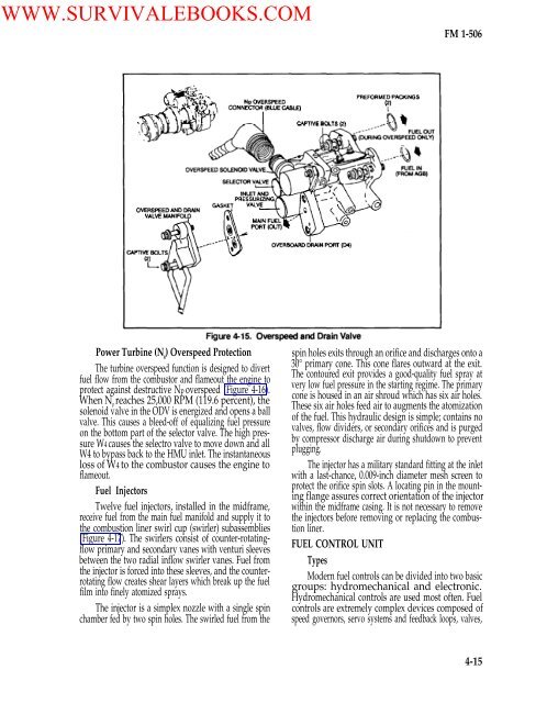
WWW.SURVIVALEBOOKS.COM<strong>FM</strong> 1-<strong>506</strong><strong>Power</strong> Turbine (N g) Overspeed ProtectionThe turbine overspeed function is designed to divertfuel flow from the combustor and flameout the engine toprotect against destructive Np overspeed (Figure 4-16).When N preaches 25,000 RPM (119.6 percent), thesolenoid valve in the ODV is energized and opens a ballvalve. This causes a bleed-<strong>of</strong>f <strong>of</strong> equalizing fuel pressureon the bottom part <strong>of</strong> the selector valve. The high pressureW4 causes the selectro valve to move down and allW4 to bypass back to the HMU inlet. The instantaneousloss <strong>of</strong> W4 to the combustor causes the engine t<strong>of</strong>lameout.Fuel InjectorsTwelve fuel injectors, installed in the midframe,receive fuel from the main fuel manifold and supply it tothe combustion liner swirl cup (swirler) subassemblies(Figure 4-17). The swirlers consist <strong>of</strong> counter-rotatingflowprimary and secondary vanes with venturi sleevesbetween the two radial inflow swirler vanes. Fuel fromthe injector is forced into these sleeves, and the counterrotatingflow creates shear layers which break up the fuelfilm into finely atomized sprays.The injector is a simplex nozzle with a single spinchamber fed by two spin holes. The swirled fuel from thespin holes exits through an orifice and discharges onto a30° primary cone. This cone flares outward at the exit.The contoured exit provides a good-quality fuel spray atvery low fuel pressure in the starting regime. The primarycone is housed in an air shroud which has six air holes.These six air holes feed air to augments the atomization<strong>of</strong> the fuel. This hydraulic design is simple; contains novalves, flow dividers, or secondary orifices and is purgedby compressor discharge air during shutdown to preventplugging.The injector has a military standard fitting at the inletwith a last-chance, 0.009-inch diameter mesh screen toprotect the orifice spin slots. A locating pin in the mountingflange assures correct orientation <strong>of</strong> the injectorwithin the midframe casing. It is not necessary to removethe injectors before removing or replacing the combustionliner.FUEL CONTROL UNITTypesModern fuel controls can be divided into two basicgroups: hydromechanical and electronic.Hydromechanical controls are used most <strong>of</strong>ten. Fuelcontrols are extremely complex devices composed <strong>of</strong>speed governors, servo systems and feedback loops, valves,4-15


