

FM 1-506 Fundamentals of Aircraft Power Plants ... - Survival Books
FM 1-506 Fundamentals of Aircraft Power Plants ... - Survival Books
FM 1-506 Fundamentals of Aircraft Power Plants ... - Survival Books

You also want an ePaper? Increase the reach of your titles
YUMPU automatically turns print PDFs into web optimized ePapers that Google loves.
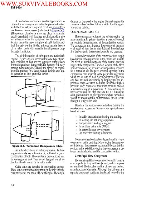
WWW.SURVIVALEBOOKS.COM<strong>FM</strong> 1-<strong>506</strong>A divided entrance <strong>of</strong>fers greater opportunity toditluse the incoming air and enter the plenum chamberwith the low velocity required to utilize efficiently adouble-entry compressor (refer back to Figure 3-3).(The plenum chamber is a storage place for ram air,usually associated with fuselage installations.) It is alsoadvantageous when the equipment installation or pilotlocation makes the use <strong>of</strong> a single or straight duct impractical.Inmost cases the divided entrance permits the use<strong>of</strong> very short ducts with a resultant small pressure dropthrough skin fiction.The air inlet section <strong>of</strong> turboprop and turboshaftengines (Figure 3-6) also incorporates some type <strong>of</strong> particleseparator or inlet screens to protect compressorsfrom foreign object damage (FOD). Systems will varyamong manufacturers. Consult the aircraft or enginetechnical manuals for a description . <strong>of</strong> the inlet duct andits particular air inlet protective device.Air inlet ducts have an anti-icing system. Turbineengine air inlets use hot engine oil, hot bleed air, or acombination <strong>of</strong> both These systems prevent icing in aturbine engine air inlet. They are not designed to melt icethat has already formed on or in the inlets.Guide vanes are included in some turbine enginesThese vanes direct air coming through the inlet into thecompressor at the most efficient angle. The angledepends on the speed <strong>of</strong> the engine. On most engines thevanes are hollow to allow hot air or oil to flow through toprevent ice buildup.COMPRESSOR SECTIONThe compressor section <strong>of</strong> the turbine engine hasmany functions. Its primary function is to supply enoughair to satisfy the requirements <strong>of</strong> the combustion burners.The compressor must increase the pressure <strong>of</strong> the mass<strong>of</strong> air received from the air inlet duct and then dischargeit to the burners in the required quantity and pressure.A secondary function <strong>of</strong> the compressor is to supplybleed air for various purposes in the engine and aircraft.The bleed air is taken nom any <strong>of</strong> the various pressurestages <strong>of</strong> the compressor. The exact location <strong>of</strong> the bleedport depends on the pressure or temperature requiredfor a particular job. The ports are small openings in thecompressor case adjacent to the particular stage fromwhich the air is to be bled. Varying degrees <strong>of</strong> pressureand heat are available simply by tapping into the appropriatestage. Air <strong>of</strong>ten bled from the final or highestpressure stage because at this point pressure and airtemperature are at a maximum. At times it may benecessary to cool this high-pressure air. If it is used forcabin pressurization or other purposes where excess heatwould be uncomfortable or detrimental the air is sentthrough a refrigeration unit.Bleed air has various uses including driving theremote-driven accessories. Some current applications <strong>of</strong>bleed air are–In cabin pressurization heating and cooling.In deicing and anti-icing equipment.For pneumatic starting <strong>of</strong> engines.In auxiliary drive units (ADUs).In control booster servo systems.As power for running instruments.Compressor section location depends on the type <strong>of</strong>compressor. In the centrifugal-flow engine the compressoris between the accessory section and the combustionsection; in the axial-flow engine the compressor is betweenthe air inlet duct and the combustion section.Centrifugal-Flow CompressorThe centrifugal-flow compressor basically consists<strong>of</strong> an impeller (rotor), a diffuser (stator), and a compressormanifold. The impeller and the diffuser are the twomain functional elements. Although the diffuser is aseparate component positioned inside and secured to the3-4


