WWW.SURVIVALEBOOKS.COM<strong>FM</strong> 1-<strong>506</strong>air pressure entering the compressor. EPR then indicatesthe ratio <strong>of</strong> these pressures. Engines instrumentedfor EPR have a fixed exhaust nozzle area. Some militaryafterburning engines have two fixed areas. One is usedfor non-afterburning operation. A variable nozzle areais used for some afterburning engines, but it varies onlywhile in afterburning. On both afterburning and nonafterburningengines, RPM and EGT may vary when theaircraft throttle is adjusted to obtain desired enginethrust.Some military afterburning models have exhaustnozzles which are scheduled to vary the exhaust areawhen the engine is running. Consequently, these enginescannot be operated to EPR settings. They must becontrolled by throttle position with various engineparameters checked to assure correct thrust output.For engines with a fixed nozzle area, actual exhaustgas temperatures obtained during operation are usuallybelow prescribed limits. It is permissible for an engine tooperate at the temperature limit for any given thrustrating. However, an engine that does may have a problemwhich causes it to run abnormally hot.With the exception noted in the use <strong>of</strong> thetachometer, engine RPM is considered a very inadequateparameter for setting and checking engine thrust onsingle and dual axial-flow compressor turbojet and turb<strong>of</strong>anengines having fixed exhaust nozzle areas. WhenRPM is used as the controlling variable on such engines,complications arise. The most important are –RPM does not provide an accurate means <strong>of</strong>determining if the complete engine is functioningproperly. High- pressure RPM on dualaxial-flow compressor engines and the RPM <strong>of</strong>the whole compressor on single axial-flow compressorengines is governed by fuel control. Forexample, RPM alone will not enable an engineoperator to detect a damaged or dirty compressor.RPM carefully used in conjunction withother engine variables such as fuel flow, exhaustgas temperature, and engine pressure ratioallow for detection.RPM for any given thrust condition will varyslightly among individual engines, dependingupon the engine trim speed. Engines aretrimmed by a fuel control adjustment toproduce full rated thrust at a fixed-throttle positionon a standard day. The RPM variationmust be taken into account when RPM is usedto measure thrust being developed by the engine.This causes a complication which cannotbe tolerated when precise thrust settings arenecessary during flight.On dual axial-flow compressor engines, RPMvariation <strong>of</strong> one percent causes approximatelyfour percent variation in thrust at the higherthrust settings for the low-pressure compressorrotor (N1) and five percent variation for thehigh-pressure compressor rotor (N2). One percentvariation in turbine discharge pressure orengine pressure ratio results in only one andone-half percent variation in thrust. The fivepercent variation in thrust for one percent variationin RPM also holds true for single axial-flowcompressor engines.RPM does not vary in direct proportion tothrust produced by the engine over the entirethrust range.For these reasons, either turbine discharge pressureor engine pressure ratio must be used as the enginevariable to indicate thrust on axial-flow compressor engineswith fixed area exhaust nozzles. The use <strong>of</strong> eitheris simpler undermost conditions and is more accurate.MEASURING POWER AND THRUST FORTURBOPROPSFor engines other than those with fully variable exhaustnozzles, turbine discharge pressure, engine pressure,or engine pressure ratio can be used with goodresults to indicate or set engine thrust. They vary proportionallyto the thrust the engine is developing. Mostturbojet and turb<strong>of</strong>an aircraft today are instrumented forengine pressure ratio. This is the parameter generallyused to set or measure engine thrust during take<strong>of</strong>f, climb,and cruise. For very accurate thrust measurement, suchas during ground trimming <strong>of</strong> an engine, turbine dischargepressure is <strong>of</strong>ten used to measure thrust. In suchcases, it is common practice to temporarily connect aturbine discharge pressure indicator to the engine.ENGINE PRESSURE RATIO INDICATINGSYSTEMIn a typical engine pressure ratio indicating system,the indicator is a dual-synchro instrument. The systemshows a constant reading <strong>of</strong> engine performance. This isdone by computing the ratio between the gas generatordischarge pressure and the inlet pressure <strong>of</strong> the engine.These ratios are then transmitted to an indicator (bothindicators if a two-engine aircraft). Sample pressures aretaken from engine gas producer or gas generator portsand from the pilot pressure system. The system includesa transducer. The transducer includes a mounting9-10
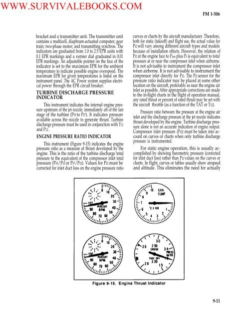
WWW.SURVIVALEBOOKS.COM<strong>FM</strong> 1-<strong>506</strong>bracket and a transmitter unit. The transmitter unitcontains a multicell, diaphram-actuated computer; geartrain; two-phase motor; and transmitting synchros. Theindicators are graduated from 1.0 to 2.5 EPR units with0.1 EPR markings and a vernier dial graduated in 0.01EPR markings. An adjustable pointer on the face <strong>of</strong> theindicator is set to the maximum EPR for the ambienttemperature to indicate possible engine overspeed. Themaximum EPR for given temperatures is listed on theinstrument panel. The AC <strong>Power</strong> system supplies electricalpower through the EPR circuit breaker.TURBINE DISCHARGE PRESSUREINDICATORThis instrument indicates the internal engine pressureupstream <strong>of</strong> the jet nozzle, immediately aft <strong>of</strong> the laststage <strong>of</strong> the turbine (Pt5 to Pt7). It indicates pressureavailable across the nozzle to generate thrust. Turbinedischarge pressure must be used in conjunction with T12and P12.ENGINE PRESSURE RATIO INDICATORThis instrument (Figure 9-15) indicates the enginepressure ratio as a measure <strong>of</strong> thrust developed by theengine. This is the ratio <strong>of</strong> the turbine discharge totalpressure to the equivalent <strong>of</strong> the compressor inlet totalpressure (Pt5/Pt2 or Pt7/Pt2). Values for Pt2 must becorrected for inlet duct loss on the engine pressure ratiocurves or charts by the aircraft manufacturer. Therefore,both for static (take<strong>of</strong>f) and flight use, the actual value forPt2 will vary among different aircraft types and modelsbecause <strong>of</strong> installation effects. However, the relation <strong>of</strong>Pt2 at the engine face to Pam plus Pr is equivalent to totalpressure at or near the compressor inlet when airborne.It is not advisable to instrument the compressor inletwhen airborne. It is not advisable to instrument thecompressor inlet directly for Pt2. The Pt2 sensor for thepressure ratio indicator may be placed at some otherlocation on the aircraft, preferably as near the engine airinlet as possible. After appropriate corrections are madeto the in-flight charts in the flight <strong>of</strong> operation manual,any rated thrust or percent <strong>of</strong> rated thrust may be set withthe aircraft throttle (as a function <strong>of</strong> the TAT or Tt2).Pressure ratio between the pressure at the engine airinlet and the discharge pressure at the jet nozzle indicatesthrust developed by the engine. Turbine discharge pressurealone is not an accurate indication <strong>of</strong> engine output.Compressor inlet pressure (Pt2) must be taken into accounton curves or charts when only turbine dischargepressure is instrumented.For static engine operation, this is usually accomplishedby showing barometric pressure (correctedfor inlet duct loss) rather than Pt2 values on the curves orcharts. In flight, curves or tables usually show airspeedand altitude. This eliminates the need for actually9-11