

FM 1-506 Fundamentals of Aircraft Power Plants ... - Survival Books
FM 1-506 Fundamentals of Aircraft Power Plants ... - Survival Books
FM 1-506 Fundamentals of Aircraft Power Plants ... - Survival Books

Create successful ePaper yourself
Turn your PDF publications into a flip-book with our unique Google optimized e-Paper software.
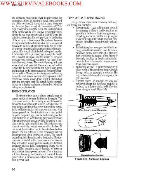
WWW.SURVIVALEBOOKS.COM<strong>FM</strong> 1-<strong>506</strong>the turbine to rotate on its shaft. To provide for thecontinuous airflow, an opening is placed in the forwardend <strong>of</strong> the container(D). A mechanical pump (compressor)forces air (solid arrow) into the container (E).Withhigh-velocity air driving the turbin, the rotating motion<strong>of</strong> the turbine can be used to drive the compressor byjoining the two rotating parts with a shaft (F). Up to thispoint the air container has only provided for the heating<strong>of</strong> the air by an outside means. The container becomesan engine combustion chamber when fuel is introducedmixed with the air, and ignited internally. Not all <strong>of</strong> theair entering the combustion chamber is needed for combustion.However, all <strong>of</strong> it is heated and expands rapidly.It exhausts as hot, high-velocity gas through the nozzleand is directed (impinged) onto the turbine. As the gasespass across the turbine, approximately two-thirds <strong>of</strong> theavailable energy is used The remaining energy still possessesa high work potential. Therefore, a second turbineis placed in the flow path <strong>of</strong> the hot, high-velocity gasesand is driven in the same manner as the comprcssordriventurbine. The second turbine (power turbine), bymeans <strong>of</strong> a shaft system mechanically independent <strong>of</strong> thecompressor turbine system drives a system <strong>of</strong> reductiongears and the output shaft. The output shaft is externallysplined for turboprop application or internallys splined forhelicopter application (G).ENGINE OPERATIONThe front or inlet duct is almost entirely open topermit outside air to enter the front <strong>of</strong> the engine. Thecompressor works on the incoming air and delivers it tothe combustion section with as much as twelve times ormore the pressure the air had when it entered the engine.In the combustion section fuel is sprayed and mixed withthe compressed air. The air-fuel mixture is then ignitedby igniter or spark plugs. Once the mixture is lighted theigniter is turned <strong>of</strong>f as the burning process will continuewithout further assistance, providing the engine is suppliedwith the right air-fuel mixture. This air-fuel mixturebums at a relatively constant pressure with only about 25percent <strong>of</strong> the air taking part in the actual combustionprocess The rest <strong>of</strong> the air is used for cooling some <strong>of</strong>the components <strong>of</strong> the combustion section, This heatedexpanding air is then directed to the turbine. The turbinesare connected to the compressor and accessoriesThey will extract a major portion (nearly two-thirds) <strong>of</strong>the energy to drive them. The remaining energy will beused to either propel the aircraft through a jet nozzle orto turn other times (power turbines). <strong>Power</strong> turbineswill take this energy and transform it into shaft horsepower,which in turn drives an output shaft or propellerfrom a power shaft.TYPES OF GAS TURBINE ENGINESThe gas turbine engines most commonly used todayare divided into four types:Turbojet engine – a gas turbine engine in whichthe net energy available is used by the air or hotgas solely in the form <strong>of</strong> the jet issuing through apropelling nozzle or nozzles or a jet enginewhose air is supplied by aturbine-driven compressor,the turbine being driven by exhaustgases.Turboshaft engine– an engine in which the netenergy available is transmitted from the exhaustgas-driven turbine wheel through a planetarygear, which may be integral to the engine orexternally provided by the aircraft manufacturer,to turn a helicopter transmissiondrivenpowertrain system.Turboprop engine – a turboshaft engine inwhich power is transferred from the power shaftthrough reduction gearing to a propeller. Themajor difference between the two engines is thegear reduction.Turb<strong>of</strong>an engine – in principle, the same as aturboprop, except that the geared propeller isreplaced by a duct-enclosed axial-flow fandriven at engine speed (Figure 3-2).3-2


