

FM 1-506 Fundamentals of Aircraft Power Plants ... - Survival Books
FM 1-506 Fundamentals of Aircraft Power Plants ... - Survival Books
FM 1-506 Fundamentals of Aircraft Power Plants ... - Survival Books

Create successful ePaper yourself
Turn your PDF publications into a flip-book with our unique Google optimized e-Paper software.
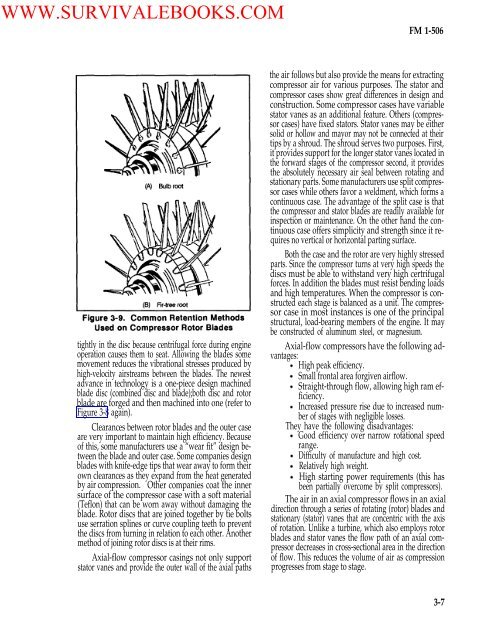
WWW.SURVIVALEBOOKS.COM<strong>FM</strong> 1-<strong>506</strong>tightly in the disc because centrifugal force during engineoperation causes them to seat. Allowing the blades somemovement reduces the vibrational stresses produced byhigh-velocity airstreams between the blades. The newestadvance in technology is a one-piece design machinedblade disc (combined disc and blade);both disc and rotorblade are forged and then machined into one (refer toFigure 3-8 again).Clearances between rotor blades and the outer caseare very important to maintain high efficiency. Because<strong>of</strong> this, some manufacturers use a “wear fit” design betweenthe blade and outer case. Some companies designblades with knife-edge tips that wear away to form theirown clearances as they expand from the heat generatedby air compression. Other companies coat the innersurface <strong>of</strong> the compressor case with a s<strong>of</strong>t material(Teflon) that can be worn away without damaging theblade. Rotor discs that are joined together by tie boltsuse serration splines or curve coupling teeth to preventthe discs from turning in relation to each other. Anothermethod <strong>of</strong> joining rotor discs is at their rims.Axial-flow compressor casings not only supportstator vanes and provide the outer wall <strong>of</strong> the axial pathsthe air follows but also provide the means for extractingcompressor air for various purposes. The stator andcompressor cases show great differences in design andconstruction. Some compressor cases have variablestator vanes as an additional feature. Others (compressorcases) have fixed stators. Stator vanes may be eithersolid or hollow and mayor may not be connected at theirtips by a shroud. The shroud serves two purposes. First,it provides support for the longer stator vanes located inthe forward stages <strong>of</strong> the compressor second, it providesthe absolutely necessary air seal between rotating andstationary parts. Some manufacturers use split compressorcases while others favor a weldment, which forms acontinuous case. The advantage <strong>of</strong> the split case is thatthe compressor and stator blades are readily available forinspection or maintenance. On the other hand the continuouscase <strong>of</strong>fers simplicity and strength since it requiresno vertical or horizontal parting surface.Both the case and the rotor are very highly stressedparts. Since the compressor turns at very high speeds thediscs must be able to withstand very high certrifugalforces. In addition the blades must resist bending loadsand high temperatures. When the compressor is constructedeach stage is balanced as a unit. The compressorcase in most instances is one <strong>of</strong> the principalstructural, load-bearing members <strong>of</strong> the engine. It maybe constructed <strong>of</strong> aluminum steel, or magnesium.Axial-flow compressors have the following advantages:High peak efficiency.Small frontal area forgiven airflow.Straight-through flow, allowing high ram efficiency.Increased pressure rise due to increased number<strong>of</strong> stages with negligible losses.They have the following disadvantages:Good efficiency over narrow rotational speedrange.Difficulty <strong>of</strong> manufacture and high cost.Relatively high weight.High starting power requirements (this hasbeen partially overcome by split compressors).The air in an axial compressor flows in an axialdirection through a series <strong>of</strong> rotating (rotor) blades andstationary (stator) vanes that are concentric with the axis<strong>of</strong> rotation. Unlike a turbine, which also employs rotorblades and stator vanes the flow path <strong>of</strong> an axial compressordecreases in cross-sectional area in the direction<strong>of</strong> flow. This reduces the volume <strong>of</strong> air as compressionprogresses from stage to stage.3-7


