

FM 1-506 Fundamentals of Aircraft Power Plants ... - Survival Books
FM 1-506 Fundamentals of Aircraft Power Plants ... - Survival Books
FM 1-506 Fundamentals of Aircraft Power Plants ... - Survival Books

Create successful ePaper yourself
Turn your PDF publications into a flip-book with our unique Google optimized e-Paper software.
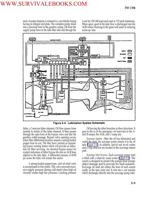
WWW.SURVIVALEBOOKS.COM<strong>FM</strong> 1-<strong>506</strong>stack <strong>of</strong> pump elements is retained in a cast tubular hosinghaving an integral end plate. The complete pump slidesinto a precision bore in the gearbox casing. Oil from thesupply pump flows to the lube filter inlet and through theis set for 120-180 psid and reset is 115 psid minimum.When open, apart <strong>of</strong> the lube flow is discharged into theAGB where churning in the gears will assist in reducingwarm-up time.falter, a 3-micron falter element. Oil flow passes fromoutside to inside <strong>of</strong> the falter element. It then passesthrough the open bore <strong>of</strong> the bypass valve and into thegearbox outlet passage. Bypass valve opening occurswhen filter differential pressure unseats a spring-loadedpoppet from its scat. The filter bowl contains an impendingbypass warning button which will provide an indicationfor filter servicing. An electrical bypass sensor forcockpit indication <strong>of</strong> falter bypass tits into an AGB bossadjacent to the lube falter. A differential pressure <strong>of</strong> 60-80psi across the falter will actuate this sensor.A spring-loaded poppet-type, cold oil relief valveis incorporated in this sytem. This valve prevents excessivesupply pressure during cold starts when high oilviscosity creates high line pressures. Cracking pressureOil leaving the falter branches in three directions. Itgoes to the to <strong>of</strong> the emergency oil reservoirs in the A-and B-sumps, the AGB, and C-sump jets.Scavenge System. After the oil has lubricated andcooled the parts, the scavenge system returns it to the oiltank (Figure 5-10). In addition, fuel-oil and air-oil coolersand a chip detector are located in the scavenge returnpath.Scavenge Inlet Screens. Each scavenge pump inletis fitted with a relatively coarse screen (Figure 5-11). Thisscreen is designed to protect the pumps from foreignobject damage and to provide for fault isolation.Scavenge oil (and air) enters the bore <strong>of</strong> each screenaxially on the open inner end. It exits into a cast annuluswhich discharges directly into the scavenge pump inlet.5-9


