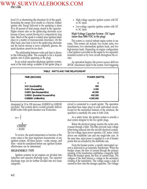
WWW.SURVIVALEBOOKS.COM<strong>FM</strong> 1-<strong>506</strong>level (1) or shortening the duration (t) <strong>of</strong> the spark.Increasing the energy level results in a heavier, bulkierignition unit. Energy delivered to the sparkplug is about30 to 40 percent <strong>of</strong> total energy stored in the capacitor.Higher erosion rates on the igniter-plug electrodes occurbecause <strong>of</strong> heavy current flowing for a comparatively longtime. Much <strong>of</strong> the spark is wasted since ignition takesplace in a matter <strong>of</strong> microseconds (microsec). On theother hand, since heat is lost to the igniter-plug electrodesand the fuel-air mixture is never completely gaseous, thespark duration cannot be too short.The relationship between watts and time is shownin the following table. The example is for a 4-jouleignition unit (4 joules appearing at the plug).In an actual capacitor-discharge ignition system,most <strong>of</strong> the total energy available to the igniter plug isHigh-voltage capacitor ignition system with DCor AC input.Low-voltage capacitor ignition system with DCor AC input.High-Voltage Capacitor System - DC input(more than 5000 VDC to the plug)This system is a typical turbojet engine system in usetoday. This system can include: two exciter units, twotransformers, two intermediate ignition leads, and twohigh-tension leads. Depending on engine configurationa dual ignition is provided on the engine by two separatelymounted exciters or by twin circuits throughout the exciter.As operation begins, the power source delivers28VDC (maximum) input to the system. Each triggeringdissipated in 10 to 100 microsec (0.000010 to 0.000100seconds). The system above would actually deliver80,000 watts if the spark duration was 50 microsec.1w= t4=0.000050= 80,000To review, the spark temperature (a function <strong>of</strong> thewatts value) is the most important characteristic <strong>of</strong> anyignition system. All three factors – watts, energy, andtime – must be considered before any ignition systemeffectiveness can be determinedHIGH-ENERGY TYPEIgnition systems for jet engines are divided intoinduction and capacitor discharge types. The capacitordischarge type can be further divided into two basiccategories:circuit is connected to a spark igniter. The operationdescribed here takes place in each individual circuit.Except for the mechanical features <strong>of</strong> the armature, theoperation is essentially the same in both Units.As a safety factor, the ignition system is actually adual system designed to fire two igniter plugs.Before the electrical energy reaches the exciter unit,it passes through a falter. This filter prevents noise voltagefrom being induced into the aircraft electrical system.The low-voltage input power operates a DC motor, whichdrives one multilobe cam and one single-lobe cam. Atthe same time, input power is supplied to a set <strong>of</strong> breakerpoints that are actuated by the multilobe cam.From the breaker points, a rapidly interrupted currentis delivered to an automatic transformer. When thebreaker closes, the flow <strong>of</strong> current through the primarywinding <strong>of</strong> the transformer establishes a magnetic fieldWhen the breaker opens, the flow <strong>of</strong> current stops. Thecollapse <strong>of</strong> the field induces a voltage in the secondarywinding <strong>of</strong> the transformer. This voltage causes a puke <strong>of</strong>current to flow into the storage capacitor. The voltage6-2
WWW.SURVIVALEBOOKS.COM<strong>FM</strong> 1-<strong>506</strong>flows through the rectifier, which limits the flow to a singledirection. With repeated pulses the storage capacitorassumes a charge up to a maximum <strong>of</strong> 4 joules. (One jouleper second equals 1 watt.)The storage capacitor is connected to the sparkigniter through the triggering transformer and a contactor,normally open. When the charge on the capacitorbuilds up, the contactor is closed by the mechanical action<strong>of</strong> the single-lobe cam. A portion <strong>of</strong> the charge flowsthrough the primary <strong>of</strong> the triggering transformer and thecapacitor connected in series with it.This current induces a high voltage in the secondarywhich ionizes the gap at the spark igniter. When the sparkigniter is made conductive, the storage capacitor dischargesthe remainder <strong>of</strong> its accumulated energy. Thisis done together with the charge from the capacitor inseries with the primary <strong>of</strong> the triggering transformer.The spark rate at the spark igniter varies in proportionto the voltage <strong>of</strong> the DC power supply, which affectsthe RPM <strong>of</strong> the motor. However, since both cams aregeared to the same shaft, the storage capacitor alwaysaccumulates its store <strong>of</strong> energy from the same number <strong>of</strong>pukes before discharge.The employment <strong>of</strong> the high-frequency triggeringtransformer, with a low-reactance secondary winding,holds the duration <strong>of</strong> the discharge to a minimum. Thisconcentration <strong>of</strong> maximum energy in minimum timeachieves an optimum spark for ignition. An optimumspark is capable <strong>of</strong> blasting carbon deposits and vaporizingglobules <strong>of</strong> fuel.All high voltage in the triggering circuits is completelyisolated from the primary circuits. The completeexciter is hermetically sealed, protecting all componentsfrom adverse operating conditions and eliminatingflashover at altitude due to pressure change. This alsoensures shielding against leakage <strong>of</strong> high-frequency voltageinterfering with the radio reception.Two igniter plugs are mounted in the combustionsection outer case. The spark igniters are generally locatedin two diametrically opposite combustion liners.The igniters receive the electrical output from the ignitionexciter unit. The igniters discharge the electrical outputfrom the ignition exciter unit. And they discharge theelectric energy during engine starting to ignite the fuel-airmixture in the combustion liners.Typical specifications for this system are as followsInput voltage: Normal: 24VDCOperating limits: 14 to 30 VDCSpark rate:Designed to fire:4 to 8 per second at each plug,depending on input voltage2 igniter plugsAccumulatedenergy3 joulesDuty cycle: 2 minutes ON, 3 minutes 0FF,2 minutes ON, 23 minutes OFFHigh-Voltage Capacitor System-AC Input<strong>Power</strong> is supplied to the unit input connector fromthe 115-volt, 400-cycle source in the aircraft. <strong>Power</strong> is firstled through a filter which blocks conducted noise voltagefrom feeding back into the airplane electrical system.From the filter, the circuit is completed through theprimary <strong>of</strong> the power transformer to groundIn the secondary <strong>of</strong> the power transformer, an alternatingvoltage is generated at a level approximating 1700volts. During the first half-cycle this follows a circuitthrough the doubler capacitor and rectifier A to ground,leaving the capacitor charged. During the second halfcyclewhen the polarity reverses, this circuit is blocked byrectifier A. The flow <strong>of</strong> this puke is through ground tothe storage capacitor, rectifier B, resistor, doublercapacitor, and back to the power transformer.With each pulse the storage capacitor assumes agreater charge. By virture <strong>of</strong> the action <strong>of</strong> the doublercapacitor, the charge approaches voltage approximatelytwice that generated in the power transformer. When thisvoltage reaches the predetermined level calibrated forthe spark gap in the discharge tube X (the control gap),the gap breaks down. This allows a portion <strong>of</strong> the accumulatedcharge to flow through the primary <strong>of</strong> thehigh-tension transformer and the trigger capacitor inseries with it. This surge <strong>of</strong> current induces a very highvoltage in the secondary <strong>of</strong> the high-tension transformer.This surge is enough to ionize the gap in discharge tube Y.The storage capacitor immediately discharges theremainder <strong>of</strong> its accumulated energy through the sparkigniter. This produces a capacitive spark <strong>of</strong> very highenergy.The bleeder resistors are provided to dissipate theresidual charge on the trigger capacitor. This is accomplishedbetween the completion <strong>of</strong> one discharge atthe spark igniter and the succession <strong>of</strong> the next cycle.Typical specifications for this system are as follows:Input voltage: Normal: 115-volts, 400-cycleACOperating limits 90 to 1241 volts6-3