

FM 1-506 Fundamentals of Aircraft Power Plants ... - Survival Books
FM 1-506 Fundamentals of Aircraft Power Plants ... - Survival Books
FM 1-506 Fundamentals of Aircraft Power Plants ... - Survival Books

Create successful ePaper yourself
Turn your PDF publications into a flip-book with our unique Google optimized e-Paper software.
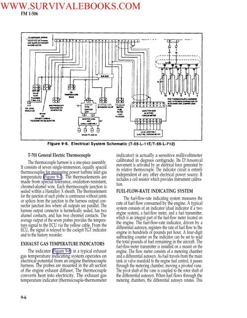
WWW.SURVIVALEBOOKS.COM<strong>FM</strong> 1-<strong>506</strong>T-701 General Electric ThermocoupleThe thermocouple harness is a one-piece assembly.It consists <strong>of</strong> seven single-immersion, equally spacedthermocouples for measuring power turbine inlet gastemperature (Figure 9-7). The thermoelements aremade from special tolerance, oxidation-resistant,chromel-alumel wire. Each thermocouple junction issealed within a Hastalloy X sheath. The thermoelementfor the junction <strong>of</strong> each probe is continuous without jointsor splices from the junction to the harness output connectorjunction box where all outputs are parallel. Theharness output connector is hermetically sealed, has twoalumel contacts, and has two chromel contacts. Theaverage output <strong>of</strong> the seven probes provides the temperaturesignal to the ECU via the yellow cable. From theECU, the signal is relayed to the cockpit TGT indicatorand to the history recorder.EXHAUST GAS TEMPERATURE INDICATORSThe indicator (Figure 9-8) in a typical exhaustgas temperature indicating system operates onelectrical potential from an engine thermocoupleharness. The probes are mounted in the aft section<strong>of</strong> the engine exhaust diffuser, The thermocoupleconverts heat into electricity. The exhaust gastemperature indicator (thermocouple-thermometerindicator) is actually a sensitive millivoltmetercalibrated in degrees centigrade. Its D‘Arsonvalmovement is activated by an electrical force generated byits relative thermocouple. The indicator circuit is entirelyindependent <strong>of</strong> any other electrical power source. Itincludes a coil resistor which provides instrument calibration.FUEL-FLOW-RATE INDICATING SYSTEMThe fuel-flow-rate indicating system measures therate <strong>of</strong> fuel flow consumed by the engine. A typicalsystem consists <strong>of</strong> an indicator (dual indicator if a twoengine system), a fuel-flow meter, and a fuel transmitter,which is an integral part <strong>of</strong> the fuel-flow meter located onthe engine. The fuel-flow-rate indicator, driven by adifferential autosyn, registers the rate <strong>of</strong> fuel flow to theengine in hundreds <strong>of</strong> pounds per hour. A four-digitsubtracting counter on the indicator can be set to readthe total pounds <strong>of</strong> fuel remaining in the aircraft. Thefuel-flow-meter transmitter is installed on a mount on theengine. The flow meter consists <strong>of</strong> a metering chamberand a differential autosyn. As fuel travels from the maintank or valve manifold to the engine fuel control, it passesthrough the metering chamber, moving a pivoted vane.The pivot shaft <strong>of</strong> the vane is coupled to the rotor shaft <strong>of</strong>the differential autosyn. When fuel flows through themetering chambers, the differential autosyn rotates. This9-6


