

FM 1-506 Fundamentals of Aircraft Power Plants ... - Survival Books
FM 1-506 Fundamentals of Aircraft Power Plants ... - Survival Books
FM 1-506 Fundamentals of Aircraft Power Plants ... - Survival Books

You also want an ePaper? Increase the reach of your titles
YUMPU automatically turns print PDFs into web optimized ePapers that Google loves.
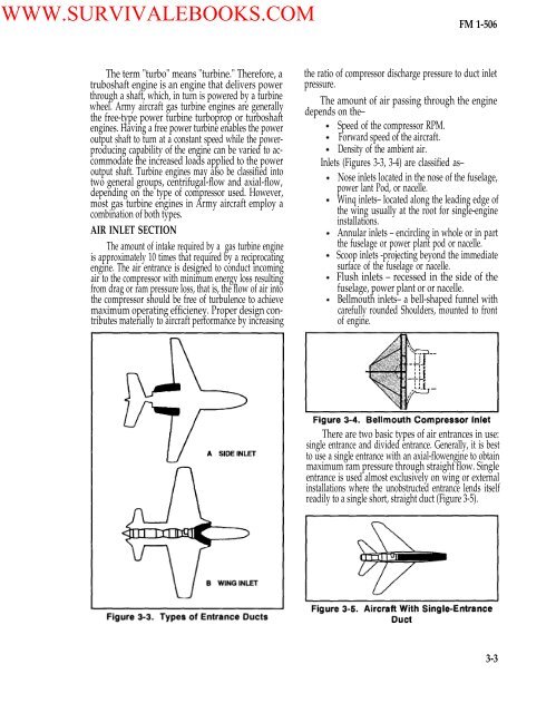
WWW.SURVIVALEBOOKS.COM<strong>FM</strong> 1-<strong>506</strong>The term "turbo" means "turbine." Therefore, atruboshaft engine is an engine that delivers powerthrough a shaft, which, in turn is powered by a turbinewheel. Army aircraft gas turbine engines are generallythe free-type power turbine turboprop or turboshaftengines. Having a free power turbine enables the poweroutput shaft to turn at a constant speed while the powerproducingcapability <strong>of</strong> the engine can be varied to accommodatethe increased loads applied to the poweroutput shaft. Turbine engines may also be classified intotwo general groups, centrifugal-flow and axial-flow,depending on the type <strong>of</strong> compressor used. However,most gas turbine engines in Army aircraft employ acombination <strong>of</strong> both types.AIR INLET SECTIONThe amount <strong>of</strong> intake required by a gas turbine engineis approximately 10 times that required by a reciprocatingengine. The air entrance is designed to conduct incomingair to the compressor with minimum energy loss resultingfrom drag or ram pressure loss, that is, the flow <strong>of</strong> air intothe compressor should be free <strong>of</strong> turbulence to achievemaximum operating efficieney. Proper design contributesmaterially to aircraft performance by increasingthe ratio <strong>of</strong> compressor discharge pressure to duct inletpressure.The amount <strong>of</strong> air passing through the enginedepends on the–Speed <strong>of</strong> the compressor RPM.Forward speed <strong>of</strong> the aircraft.Density <strong>of</strong> the ambient air.Inlets (Figures 3-3, 3-4) are classified as–Nose inlets located in the nose <strong>of</strong> the fuselage,power lant Pod, or nacelle.Winq inlets– located along the leading edge <strong>of</strong>the wing usually at the root for single-engineinstallations.Annular inlets – encircling in whole or in partthe fuselage or power plant pod or nacelle.Scoop inlets -projecting beyond the immediatesurface <strong>of</strong> the fuselage or nacelle.Flush inlets – recessed in the side <strong>of</strong> thefuselage, power plant or or nacelle.Bellmouth inlets– a bell-shaped funnel withcarefully rounded Shoulders, mounted to front<strong>of</strong> engine.There are two basic types <strong>of</strong> air entrances in use:single entrance and divided entrance. Generally, it is bestto use a single entrance with an axial-flowengine to obtainmaximum ram pressure through straight flow. Singleentrance is used almost exclusively on wing or externalinstallations where the unobstructed entrance lends itselfreadily to a single short, straight duct (Figure 3-5).3-3


